Week-7 Challenge: DC Motor Control
"Week-7 Challenge: DC Motor Control"
Aim: To study and understand DC Motor Control.
Objective:
1. A. Explain a MATLAB demo model named ‘Speed control of a DC motor using BJT H-bridge’.
B. Comment on the armature current shoot-up from the scope results.
C. Refer to the help section of ‘The Four-Quadrant Chopper DC Drive (DC7) block’. Compare it with the H-bridge model.
2. Develop a 2-quadrant chopper using Simulink & explain the working of the same with the relevant results. (Refer to article - Multiquadrant operation of motor )
3. Explain in a brief the operation of BLDC motor.
Power Semiconductors Devices:
Power Electronics is the application of semiconductor devices such as transistors, diodes, and integrated circuits(ICs) to the control and conversion of electric power.
A power electronic converter is an electronic device made of high-power semiconductor switches that use different switching states to change the magnitude and waveform of the voltage and current between the input and output.
Power semiconductor devices are widely used in automotive power electronic systems and often dictate these systems' efficiency, cost, and size. Active power semiconductor switches such as MOSFETs and IGBTs serve as load drivers for motors (ranging from 75 kW AC traction motors to 1W DC motors), solenoids, ignition coils, relays, heaters, lamps, and other automotive loads. Diodes are used in automotive systems to rectify AC generated by the alternator, provide a freewheeling current path for IGBTs or MOSFETs in DC/AC inverters and DC/DC converters, and suppress voltage transients. Nowadays, an average vehicle has over 50 actuators, which are often controlled by power MOSFETs or other power semiconductor devices.
Transistor:
A transistor is a type of semiconductor device that can be used to both conduct and insulate electric current or voltage. A transistor basically acts as a switch and an amplifier. In simple words, we can say that a transistor is a miniature device that is used to control or regulate the flow of electronic signals.
A typical transistor is composed of three layers of semiconductor materials or more specifically terminals which help to make a connection to an external circuit and carry the current. A voltage or current that is applied to any one pair of the terminals of a transistor controls the current through the other pair of terminals. There are three terminals for a transistor. They are:
- Base: This is used to activate the transistor.
- Collector: It is the positive lead of the transistor.
- Emitter: It is the negative lead of the transistor.
Transistors are commonly used in digital circuits as electronic switches, either in an "on" or "off" state, both for high-power applications such as switched-mode power switches and low-power applications such as logic gates.
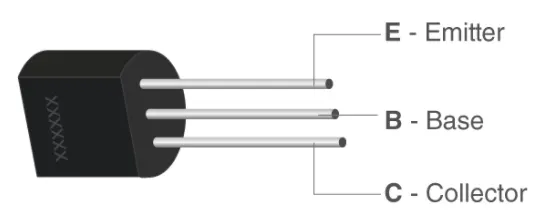
Based on how they are used in a circuit there are mainly two types of transistors.
- BJT( Bipolar junction transistors)
- FET( Field effective transistors)
Bipolar Junction Transistor (BJT):
The three terminals of BJT are base, emitter, and collector. A very small current flowing between base and emitter can control a larger flow of current between the collector and emitter terminal.
Furthermore, there are two types of BJT. These include;
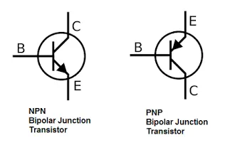
- P-N-P Transistor: It is a type of BJT where one n-type material is introduced or placed between two p-type materials. In such a configuration, the device will control the flow of current. PNP transistor consists of 2 crystal diodes which are connected in series. The right side and left side of the diodes are known as the collector-base diode and emitter-base diode, respectively.
- N-P-N Transistor: In this transistor, we will find one p-type material that is present between two n-type materials. N-P-N transistor is basically used to amplify weak signals to strong signals. In an NPN transistor, the electrons move from the emitter to the collector region resulting in the formation of current in the transistor. This transistor is widely used in the circuit.
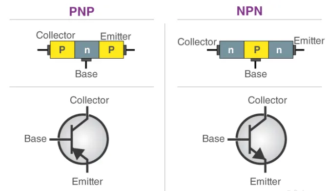
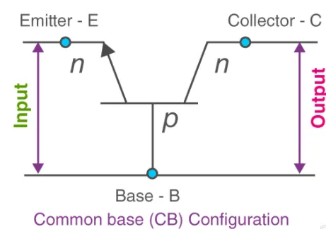
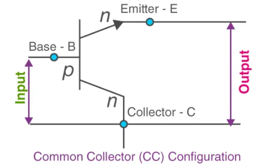
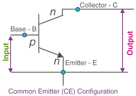
There are three types of configuration as a common base (CB), common collector (CC) and common emitter (CE).
In Common Base (CB) configuration the base terminal of the transistor is common between input and output terminals.
In Common Collector (CC) configuration the collector terminals are common between the input and output terminals.
In Common Emitter (CE) configuration the emitter terminal is common between the input and the output terminals.
MOSFET(Metal oxide semiconductor field-effect transistors):
The MOSFET (Metal Oxide Semiconductor Field Effect Transistor) transistor is a semiconductor device that is widely used for switching purposes and for the amplification of electronic signals in electronic devices. A MOSFET is either a core or integrated circuit where it is designed and fabricated in a single chip because the device is available in very small sizes. The introduction of the MOSFET device has brought a change in the domain of switching in electronics.
A MOSFET is a four-terminal device having source(S), gate (G), drain (D) and body (B) terminals. In general, The body of the MOSFET is in connection with the source terminal thus forming a three-terminal device such as a field-effect transistor. MOSFET is generally considered as a transistor and employed in both the analog and digital circuits. The general structure of this device is as below :
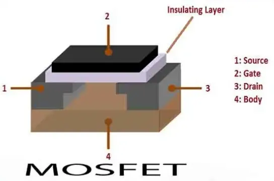
From the above MOSFET structure, the functionality of MOSFET depends on the electrical variations happening in the channel width along with the flow of carriers (either holes or electrons). The charge carriers enter into the channel through the source terminal and exit via the drain.
The width of the channel is controlled by the voltage on an electrode which is called the gate and it is located in between the source and the drain. It is insulated from the channel near an extremely thin layer of metal oxide. The MOS capacity that exists in the device is the crucial section where the entire operation is across this.
IGBT(Insulated Gate Bipolar Transistor):
IGBT is the short form of Insulated Gate Bipolar Transistor. It is a three-terminal semiconductor switching device that can be used for fast switching with high efficiency in many types of electronic devices. These devices are mostly used in amplifiers for switching/processing complex wave patters with pulse width modulation (PWM). The typical symbol of IGBT along with its image is shown below.
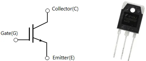
As mentioned earlier an IGBT is a fusion between a BJT and MOSFET. The symbol of the IGBT also represents the same, as you can see the input side represents a MOSFET with a Gate terminal and the output side represents a BJT with Collector and Emitter. The Collector and the Emitter are the conduction terminals and the gate is the control terminal with which the switching operation is controlled.
Power BJT(Power Bipolar Junction Transistor):
The power bipolar junction transistor (BJT) blocks a high voltage in the off state and high current carrying capacity in the on-state. The power handling capacity is very high.
The power BJT has three terminals Collector (C), Emitter (E) and Base (B). It has a vertically oriented four-layers structure. The vertical structure uses to increase the cross-sectional area.
There are two types of BJT; n-p-n transistor and p-n-p transistor. Out of these two types, the n-p-n transistors widely use compare to the p-n-p transistor.
Application:
- Switched Mode Power Supply (SMPS)
- Power Amplifier
- Relay and Drivers
- AC motor speed controller
- DC/AC inverter
- As series pass transistor in the regulated power supply
- The audio amplifier in the stereo system
- Power control circuit
| PARAMETER | BJT | MOSFET | IGBT |
| Carriers Type | Bipolar device | Majority carrier device | Bipolar device |
| Gate or base Type | Current controlled | Voltage Controlled | Voltage Controlled |
| Temperature coefficient of ON-state resistance | Negative | Positive | Positive |
| Applications | Inverters, Choppers, UPS, SMPS, induction motor drives. | Choppers, low power UPS, SMPS, brush-ess DC motor drives. | Inverters, UPS, SMPS, AC motor drives. |
| Switching Power Loss | High | Low | Low |
| Input Impedance | High | Low | Low |
| On state voltage drop and Conduction loss | Low | High | Low |
| Parallel Operation | Not Possible | Possible | Possible |
| Voltage and Current Rating | 1200 V and 800 A | 500 V and 140 A | 1200 V and 500 A |
| Switching Frequency Rating | (10 - 20) kHz | up to 1 MHz | up to 50 kHz |
H-Bridge:
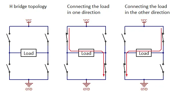
In general an H-bridge is a rather simple circuit, containing four switching element, with the load at the center, in an H-like configuration:

The switching elements (Q1..Q4) are usually bi-polar or FET transistors, in some high-voltage applications IGBTs. Integrated solutions also exist but whether the switching elements are integrated with their control circuits or not is not relevant for the most part for this discussion. The diodes (D1..D4) are called catch diodes and are usually of a Schottky type.
The top-end of the bridge is connected to a power supply (battery for example) and the bottom-end is grounded.
In general all four switching elements can be turned on and off independently, though there are some obvious restrictions.
Though the load can in theory be anything you want, by far the most pervasive application if H-bridges is with a brushed DC or bipolar stepper motor (steppers need two H-bridges per motor) load. In the following I will concentrate on applications as a brushed DC motor driver.
Static Operation:
The basic operating mode of an H-bridge is fairly simple: if Q1 and Q4 are turned on, the left lead of the motor will be connected to the power supply, while the right lead is connected to ground. Current starts flowing through the motor which energizes the motor in (let’s say) the forward direction and the motor shaft starts spinning.

If Q2 and Q3 are turned on, the reverse will happen, the motor gets energized in the reverse direction, and the shaft will start spinning backwards.

In a bridge, you should never ever close both Q1 and Q2 (or Q3 and Q4) at the same time. If you did that, you just have created a really low-resistance path between power and GND, effectively short-circuiting your power supply. This condition is called ‘shoot-through’ and is an almost guaranteed way to quickly destroy your bridge, or something else in your circuit.

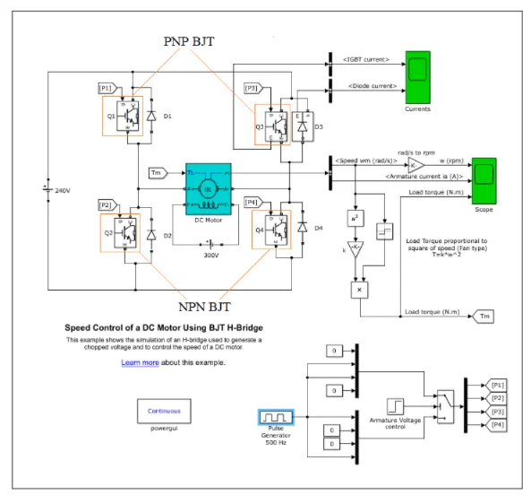
Q1).A. Explain a MATLAB demo model named ‘Speed control of a DC motor using BJT H-bridge’.
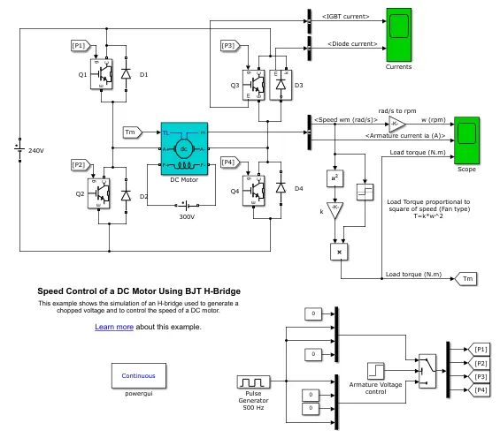
The above Speed Control of a DC motor using the BJT H-bridge Simulink model is opened in Matlab.
Blocks Used:
`rArr IGBT :`
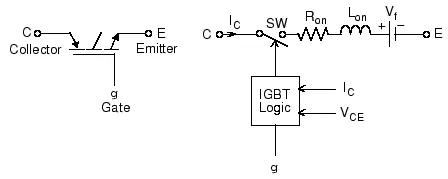
The IGBT block implements a semiconductor device controlled by the gate signal. The IGBT is simulated as a series combination of a resistor `R_(on)`, inductor `L_(on)`, and a DC voltage source `V_(f)` in series with a switch controlled by a logical signal (g > 0 or g = 0). The IGBT block contains a series `R_s-C_s` snubber circuit, which is connected in parallel with the IGBT device (between terminals C and E).
When `V_(CE) >0, V_(CE) > V_f, g >0 rarr` ON state
When `V_(CE) > 0, g = 0 rarr` OFF state
The Bipolar Junction Transistor(BJT) when used for power switching applications, operates as an IGBT. When it is conducting (BJT operating in the saturated region), a forward voltage `V_f` is developed between collector and emitter (in the range of 1V). Therefore, the IGBT block can be used to mode the BJT device.
`rArr Diode:`
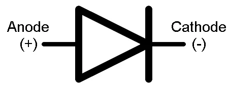
The Diode block can represent either a piecewise linear diode, an exponential diode, or a diode with a tabulated I-V curve. If the diode forward voltage exceeds the value specified in the Forward voltage parameter, the diode behaves as a linear resistor with the resistance specified in the On resistance parameter. Otherwise, the diode behaves as a linear resistor with the small conductance specified in the Off conductance parameter. Zero voltage across the diode results in zero current flowing.
`rArr`Dc Machine:
The DC Machine block implements a wound-field or permanent magnet DC machine. This block consists of 3 segments armature circuit, field circuit and a torque input-measurement signals output. The motor used here is 5HP, 240V, and 1750RPM. It simuates a fan type model, proportional to the square of speed. The armature voltage can be varied from 0 to 240V by changing the duty cycle. The duty cycle can be changed by a pulse width generator block.
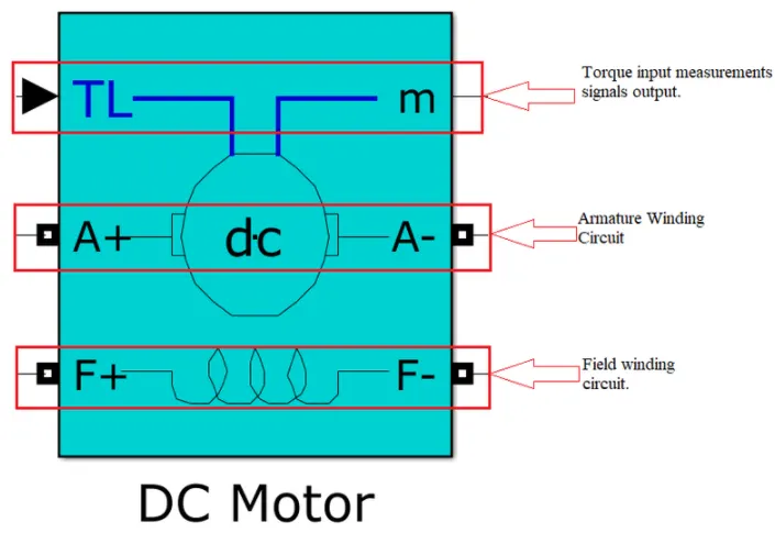
Here, the DC Machine is used as a DC motor. We need to control the DC motor's rotation in such a way that when to spin anti clockwise & when to spin clockwise and with variable speeds. For that, we use an H-bridge configuration of circuits. The name H-bridge is given as the circuit resembles the letter "H".
The circuit requires switches that can automatically turn ON/OFF very fastly as per the requirements. Hence, we use power switches. The switch used is IBJT, but the model is said to have a BJT because BJT works as IGBT as a switch.
| Base-Emitter | Base-Collector | Mode | Operation |
| Reverse | Reverse | Cut off | Switch(off) |
| Forward | Forward | Forward Active | Amplifier |
| Forward | Forward | Saturation | Switch(on) |
From the above table we can clearly see that, when the BJT is in saturation or conducting state, the Base-Emitter and Base-Collector are forward biased. Hence, the BJT act in ON state. The BJT is controlled by Simulink signals as 1 and 0. Logic "1" represents a higher voltage, such as 5 volts, which is commonly referred to as a High value, while "0" represents a low voltage, such as 0 volt or ground, and is commonly referred to as a low value. But to make this 5 volts as 1 volt, we have used IGBT block instead of BJT. The H-bridge consists of 4 transistors, namely Q1, Q2, Q3, and Q4. Each one has a snubber circuit connected in parallel.
The H-bridge works in such a way that at a time two IGBT and 2 diodes are in on state. When the IGBT's Q2 & Q3 are in conducting state and the diodes D1 & D4 act as freewheeling diodes, making the motor spin in one direction. When the IGBT's Q1 & Q4 are in conducting state and diodes D2 & D4 act as freewheeling diodes, making the motor spin in opposite direction. The motor speed can be controlled by the self-excitation voltage provided across the rotor windings(i.e 0 to 300V).
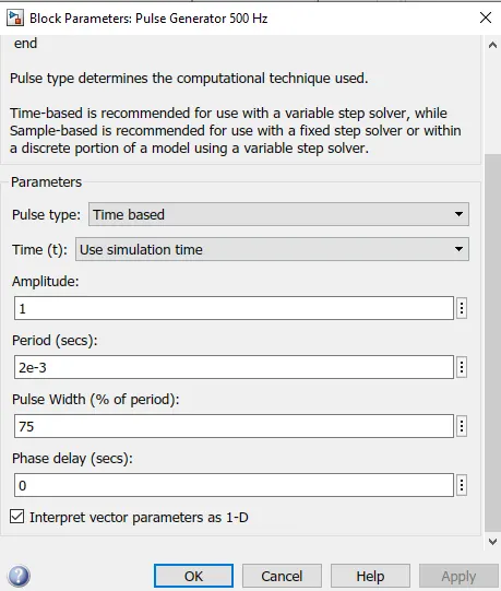
Case-1:
- Total Cycle time: 1 sec
- Duty Cycle = 75%
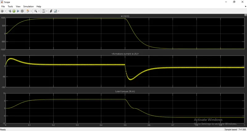
Output Plot:
Q1).B. Comment on the armature current shoot-up from the scope results.
In the above plot, the armature current has a sudden rise and drop when the motor changes direction from forward to reverse motion.
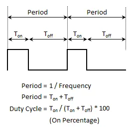
A Pulse Width Modulation(PWM) signal is a method for generating analogue signal using a digital source and a frequency. By cycling a digital signal OFF and ON at a fast enough rate, and with a certain duty cycle, the output will appear to behave like a constant voltage and current analogue signal when providing power to devices.
We can see from the first plot of speed, starts from the positive side then runs constantly at that rpm and then suddenly drops and spin in opposite direction. Simultaneously the armature current also spikes up initially at the start and also at the reversal of armature voltage causing the motor to spin in opposite direction. This happens because, by default, the armature voltage control is set at a step time of t = 0.5. It means at t = 0.5s the motor rotation will change in the reverse direction as the armature voltage will reverse.
To minimize the sudden surge in the armature current at the start and when the motor runs in reverse, we have to modify the duty cycle. The default value is 75%. This means that the voltage is supplied 75% of the time to the motor and the rest 25% the motor receives no voltage from the source and it is in OFF state. This sudden change in OFF and ON state (i.e reversal of armature voltage) causes the armature current to spike up abruptly.
Case - 2:
- Total Cycle time: 1 sec
- Duty Cycle = 50%
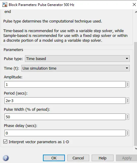
Output Plot:
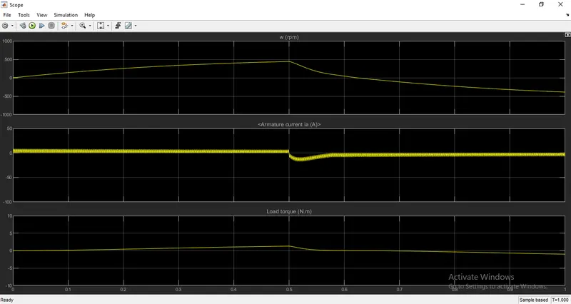
When the duty cycle is 50% there is a sudden spike in armature current when the armature voltage at t = 0.5s. But it is not at the start of the motor.
Case - 3:
- Total Cycle time: 1 sec
- Duty Cycle = 30%
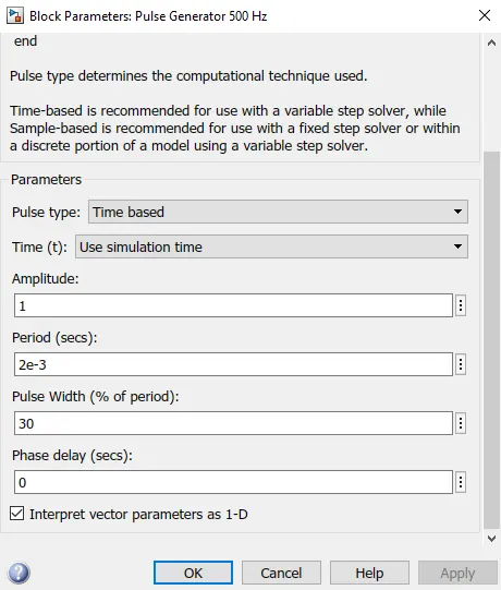
Output Plot:
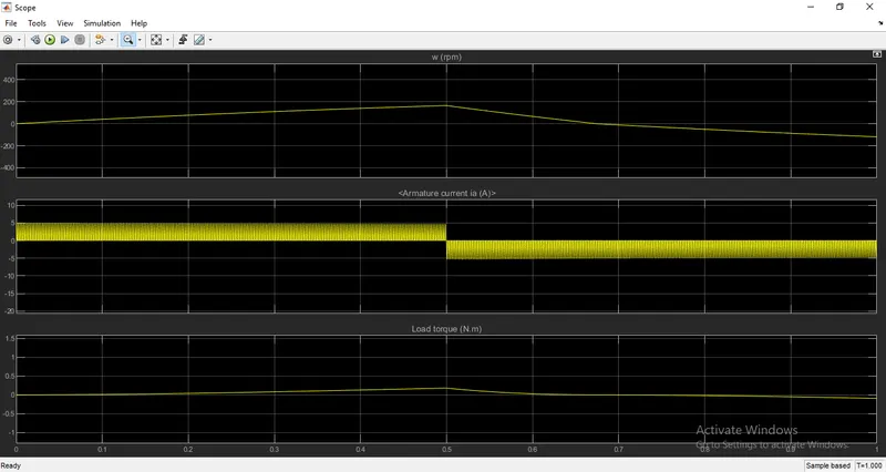
When the duty cycle is 30% the sudden surge in armature current at the start of the motor and t = 0.5s has been reduced. And the armature current is constant at approximately 5A in both +ve and -ve directions.
Q1).C.Refer to the help section of ‘The Four-Quadrant Chopper DC Drive (DC7) block’. Compare it with the H-bridge model.
In Simscape Electrical Specialized Power Systems software, the Four-Quadrant Chopper DC Drive block is commonly called the DC7 motor drive. The Four-Quadrant Chopper DC Drive (DC7) block represents a four-quadrant, DC-supplied, chopper (or DC-DC PWM converter) drive for DC motors. This drive features closed-loop speed control with a four-quadrant operation. The speed control loop outputs the reference armature current of the machine. Using a PI current controller, the chopper duty cycle corresponding to the commanded armature current is derived. This duty cycle is then compared with a sawtooth carrier signal to obtain the required PWM signals for the chopper.
The main advantage of this drive, compared with other DC drives, is that it can operate in all four quadrants. In each quadrant, its characteristics represent a different mode of operation.
The first quadrant is "Forward Motoring", the second is "Reverse Braking", the third is "Reverse Motoring" and the fourth is "Forward Braking".
In addition, due to the use of high switching frequency DC-DC converters, a lower armature current ripple (compared with thyristor-based DC drives) is obtained. However, four switching devices are required, which increases the complexity of the drive system.
The Simulink block of DC7 and its circuit diagram is given below:
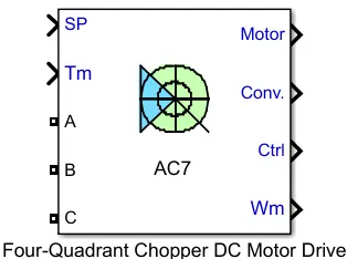
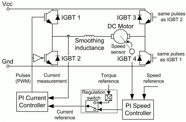
From the help section of Matlab documentation, The DC7 file or the Four-Quadrant Chopper DC drive can be found out and by opening the model file we get the Simulink blocks.
`rArr` The model is obtained by typing dc7_example in the command window. The model looks like as shown below:-
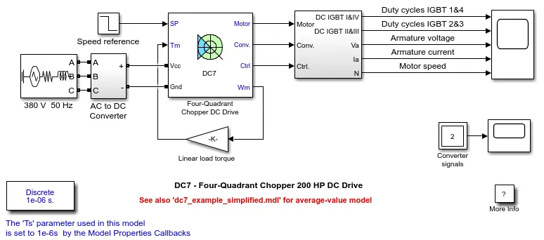
Here, the power supply is not dc. It is a 380V 50 Hz AC power supply. It means that the rotor of the generator turns 50 cycles per second, the current changes 50 times per second back and forth, direction changes 100 times. That means the 380V changes from positive to negative, and from negative to positive voltage, this process converts 50 times/second.
The model contains AC to DC converter (i.e Rectifier Bridge + Braking Chopper), Four-Quadrant Chopper DC drive, bus model subsystem. The applied AC 380V is converted to a 515V DC supply by an AC to DC converter. This converter includes a rectifier and a braking chopper. The braking chopper is used to convert the voltage from the motor while generating braking, exceeding a threshold voltage into thermal energy. This is done by the brake resistor connected in series with the diode and a switching device inside the braking chopper. The braking chopper activates when the voltage reaches 560V and it switches OFF when the voltage is 520V. Though the AC source is converted to 515V, we must include losses. Hence, the voltage is kept at 520V.
The motor run based on the speed reference block provided.
`rArr` Four-Quadrant operation of DC Motor:
A motor operates in two modes – Motoring and Braking. A motor drive capable of operating in both directions of rotation and of producing both motoring and regeneration is called a Four Quadrant variable speed drive.
In motoring mode, the machine works as a motor and converts the electrical energy into mechanical energy, supporting its motion. In braking mode, the machine works as a generator and converts mechanical energy into electrical energy and as a result, it opposes the motion. The Motor can work in both, forward and reverse directions, i.e., in motoring and braking operations.
The figure below shows the four-quadrant operation of drives:
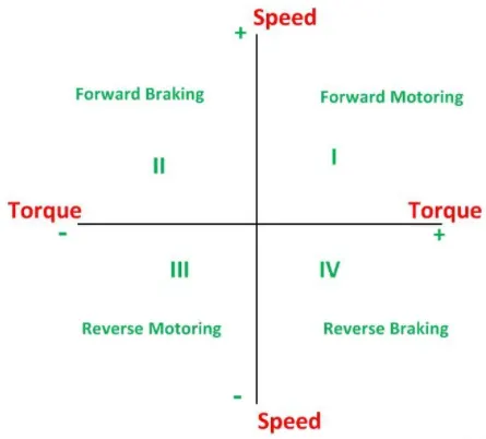
In the I quadrant power developed is positive and the machine is working as a motor supplying mechanical energy. The I (first) quadrant operation is called Forward Motoring. II (second) quadrant operation is known as Braking. In this quadrant, the direction of rotation is positive, and the torque is negative, and thus, the machine operates as a generator developing a negative torque, which opposes the motion.
The kinetic energy of the rotating parts is available as electrical energy which may be supplied back to the mains. In dynamic braking, the energy is dissipated in the resistance. The III (third) quadrant operation is known as reverse motoring. The motor works, in the reverse direction. Both the speed and the torque have negative values while the power is positive.
In the IV (fourth) quadrant, the torque is positive, and the speed is negative. This quadrant corresponds to the braking in the reverse motoring mode.
Applications of Four Quadrant Operation:
- Compressor, pump, and fan type load requires operation in the I quadrant only. As their operation is unidirectional, they are called one quadrant drive systems.
- Transportation drives require operation in both directions.
- If regeneration is necessary, application in all four quadrants may be required. If not, then the operation is restricted to quadrants I and III, and thus dynamic braking or mechanical braking may be required.
- In hoist drives, a four-quadrant operation is needed.
The four-quadrant operation and its relationship to speed, torque, and power output are summarized below in the table:
| Function | Quadrant | Speed | Torque | Power Output |
|---|---|---|---|---|
| Forward Motoring | I | + | + | + |
| Forward Braking | II | + | - | - |
| Reverse Motoring | III | - | - | + |
| Reverse Braking | IV | - | + | - |
The Four-Quadrant Chopper DC Drive block uses these blocks from the Electric Drives/Fundamental Drive Blocks library:
`rArr` Speed Controller Block:
The inputs are speed reference and motor speed and output a current reference. This output current reference is in turn used by the current controller block to obtain the electromagnetic torque needed to reach the desired speed.
`rArr` Regulation Switch Block:
The Regulation Switch block consists of a DC machine(wound-field type) torque controller model and a Simulink Switch model. The latter is used to select the regulation model, i.e. torque or speed regulation of the DC drive. The torque controller provides a DC current reference. A second reference DC current is obtained from the speed controller. Depending on the regulation mode, the Simulink switch selects between the two DC current references.
`rArr` Current Controller Block:
The Current Controller (DC) block models a PI current controller for use with a DC machine. The block has multiple instances, depending on the DC drive type (chopper DC drive or thyristor-based DC drive) and operating quadrants(one-two, or four-quadrant). It has two operating modes to represent a detailed or an average-value current controller. The DC current controller block inputs are the current reference and the armature current flowing through the motor. The outputs are current reference, duty cycles, PWM pulses, and reference current error. From here the PWM pulses are fed to the chopper block where the switches are present.
`rArr` Chopper Block:
The Chopper Block models a standard half-bridge (one leg, two IGBTs) or full-bridge(two legs, four IGBTs) converter model. It has two operating modes to represent a detailed or an average-value chopper. Each operating model has multiple instances depending on the DC motor drive type(two or four-quadrant operation). The chopper block outputs the desired armature current to the DC motor. To avoid the sudden surge in the current fluctuations, a smoothing inductance is connected in series with the chopper.
`rArr` DC Machine:
Here, the motor is coupled to a linear load, which means that the mechanical torque of the load is proportional to the speed.
Output Plot:
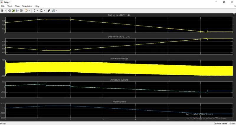
The above plot shows the motor armature voltage and current, the four IGBT pulses, and the motor speed on the scope. The current and speed references are also shown.
The motor is coupled to a linear load, which means that the mechanical torque of the load is proportional to the speed.
Advantages:
- Four-Quadrant choppers have more control over the deceleration of the motor and can more accurately brake the motor. This will make the deceleration smoother.
- It reduces the risk of current spikes, which can damage the motor and the controller itself because this can occur when the motor is made to brake while running at a high speed. So, the controller life is generally longer with Four-Quadrant choppers, by mitigating those sudden surges or spikes from the output.
- Four-Quadrant choppers are more efficient because lesser energy is wasted as heat and lesser current spikes occur which means lesser power dissipation over a complete.
- In the case of vehicles, the four-quadrant chopper makes regenerative braking possible so that when the motor is made to brake, the kinetic energy of the rotor moving is transferred back as electrical energy which can then be used to charge a battery.
Comparison:
| DC drive using BJT H-Bridge | DC drive using Four-Quadrant Chopper |
| Power switches are powered by a 240V DC supply. | Power switches are powered by a 380V 50Hz AC 3-phase supply which is converted to a 515V DC supply. |
| Field windings are separately excited by a 300V DC supply. | Field windings are separately excited by a 150V DC supply. |
| Works only in forward motoring and reverse motoring. | Here the DC motor operates in all four-quadrant - forward motoring, reverse motoring, forward braking, and revere braking. |
| It is just controlling the DC motor speed. | It is a drive that symbolizes the mechanical and power electronics components. |
| Efficiency is less. | Efficiency is more. |
| Here the torque is proportional to the square of the speed. | Here the motor is subjected to linear load. Hence the torque is just proportional to speed. |
Q2). Develop a 2-quadrant chopper using Simulink & explain the working of the same with the relevant results. (Refer to article - Multiquadrant operation of motor )
2-quadrant chopper:
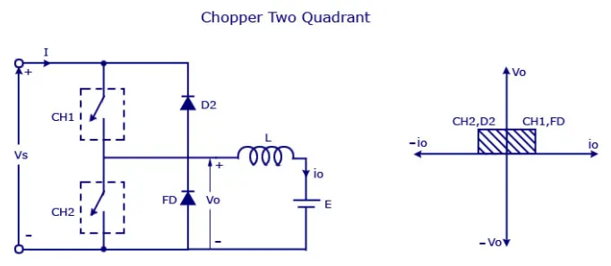
The Two-Quadrant Chopper block represents a two-quadrant controlled chopper for converting a fixed DC input to a variable DC output. In this type of Chopper, the average voltage will be always positive but the average load current might be positive or negative. The block contains two switching devices.
The two switches CH 1 and CH 2 should not be turned on simultaneously as the combined action may cause a short circuit in supply lines. For regenerative braking and motoring, this type of chopper configuration is used.
We will always get a positive output voltage V0 as the freewheeling diode FD is present across the load. When the chopper CH 1 is on the current flows from source to load. The inductor stores energy. When Ch 1 turns OFF the freewheeling diode starts conducting and the output voltage v0 will be equal to Vs·The direction of the load current i0 will be reversed. The current i0 will be flowing towards the source. The load current will be negative when the CH2 is on. The current completes its path through diode D2.
Developed a 2-quadrant chopper by using Simulink:
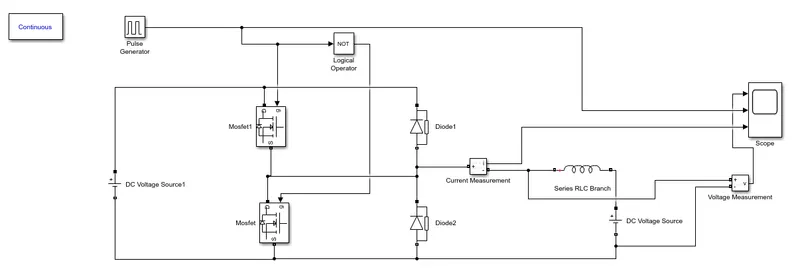
Required Block for Model Construction:
- Power GUI
- Pulse Generator
- Current Measurement
- Voltage Measurement
- Diode
- MOSFET
- DC Voltage Source
- Logical Operator (NOT)
- Series RLC Branch
- Scope
Steps for making the model:
- At first, we have arranged the Blocks as per the circuit connection shown above in the model.
- Double click on MOSFET and DIODE Block to disable (uptick show measurement port), and rotate the diode in the upward direction as per our requirement (source should be facing in the downward direction for MOSFET and upward direction for DIODE)
- Open series RLC block and change the branch type to (L) with default value 1 mil H, once done arranged according to the circuit diagram.
- Open logical operator and select NOT in Operation options, connects its input to the output of PULSE Generator block. The reason we have used NOT gate is to ensure both the Switches do not conduct simultaneously if they do so supply will be short-circuited.
- We will be giving the tapping for the PULSE gate terminal for one switch MOSFET1 and from NOT gate we are giving it to another switch MOSFET2. So, if MOSFET1 is conducting MOSFET2 will not conduct because we are using the NOT gate.
- Once done we will be measuring the voltage by connecting its 1st port at starting of the inductor and other to the DC2 supply which is connected adjacent.
- Then the output is connected to 1st of the 3 ports of scope input, the current measurement port is also connected to 2nd port of Scope, and 3rd is taken from the output of the PULSE generator.
- Double click on the main DC voltage supply and set amplitude(V) to 30v and for adjacent DC2 supply set amplitude as 12v.
- At last, we have opened the pulse generator block and set the amplitude to 10 for better viewing, time period set to 1 sec, the pulse width is 50 (because we want 50% to be ON and 50% to be OFF) i.e. NOT gate is ON when 50% is OFF.
Working of the Model:
Type C chopper is obtained by connecting type A and type B choppers in parallel. We will always get a positive output voltage Vo as the freewheeling diode FD is present across the load. When the chopper is on the freewheeling diode starts conducting and the output voltage Vo will be equal to Vs. The direction of the load current io will b reversed. The current io will be flowing towards the source and it will be positive regardless of the chopper is on or the FD conducts. The load current will be negative if the chopper is or the diode D2 conducts. We can say the chopper and FD operate together as a type A chopper in the first quadrant. In the second quadrant, the chopper and D2 will operate together as type B choppers.
The average voltage will be always positive but the average load current might be positive or negative. The power flow may be like the first quadrant operation i.e. from source to load or from load to source as the second quadrant operation. The two choppers should not be turned on simultaneously as the combined action may cause a short circuit in supply lines. For regenerative braking and motoring, this type of chopper configuration is used.
Let, the voltage of the DC voltage source be 30 volts.
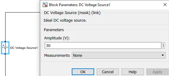
Let us consider a series RLC branch block and select inductor L. The bock works as load.
To consider LE load i.e motor load, and dc voltage source of 15 volts is also connected in series with the inductor.
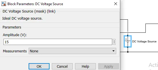
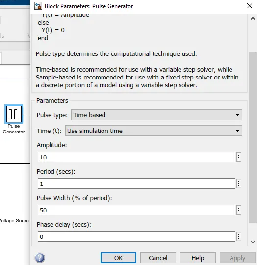
The pulse generator block is used to create gate pulse.
The NOT gate is used in the model so that the two MOSFETs will not get closed at the same time otherwise the short circuit will occur. Due to the use of the NOT gate, when one MOSFET is ON the other MOSFET will get OFF and when the other MOSFET is ON then the first MOSFET will get OFF.
The amplitude of the pulse generator is kept at 10 so that we can clearly see the pulses at the scope and let periods be 1 second and let pulse width be 50%.
Results:
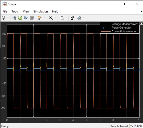
From the above graph, we can clearly see that the voltage waveform is not going less than zero, the minimum value of voltage is zero and the maximum value is 31.40 volts.
However, in the current waveform, the current increases and decreases, current may be positive as well as negative.
From the pulse waveform, we can see that the pulse amplitude is 10.
Q3. Explain in a brief about operation of BLDC motor.
BLDC Motor:
A brushless DC motor (also known as a BLDC motor or BL motor) is an electronically commuted DC motor that does not have brushes. The controller provides pulses of current to the motor windings which control the speed and torque of the synchronous motor.
These types of motors are highly efficient in producing a large amount of torque over a vast speed range. In brushless motors, permanent magnets rotate around a fixed armature and overcome the problem of connecting current to the armature. Commutation with electronics has a large scope of capabilities and flexibility. They are known for smooth operation and holding torque when stationary.
Before explaining the working of a brushless DC motor, it is better to understand the function of a brushed motor. In brushes motors, there are permanent magnets on the outside and a spinning armature that contains an electromagnet is inside. These electromagnets create a magnetic field in the armature when the power is switched on and help to rotate the armature.
The brushes change the polarity of the pole to keep the rotation on of the armature. The basic working principle for the brushed DC motor and for the brushless DC motor is the same i.e. internal shaft position feedback.
A Brushless DC motor has only two basic parts: rotor and the stator. The rotor is the rotating part and has rotor magnets whereas the stator is the stationary part and contains stator windings. In BLDC permanent magnets are attached to the rotor and move the electromagnets to the stator. The high-power transistors are used to activate electromagnets for the shaft turns. The controller performs power distribution by using a solid-state circuit.
As mentioned earlier, a BLDC motor used electronic commutation and thus eliminates the mechanically torn brushes.
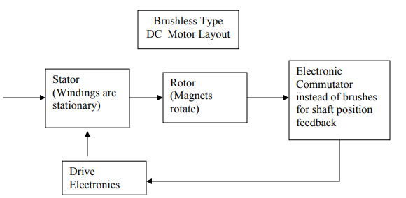
Construction of BLDC Motor:
The main design difference between brushed and brushless motors is the replacement of a mechanical commutator with an electric switch circuit. Keeping that in mind, a BLDC motor is a type of synchronous motor in the sense that the magnetic field generated by the stator and the rotor revolve at the same frequency.
BLDC motors can be constructed in different physical configurations. Depending on the stator windings, these can be configured as single-phase, two-phase, or three-phase motors. However, three-phase BLDC motors with permanent magnet rotors are most commonly used.
The following image shows the cross-section of a BLDC Motor.
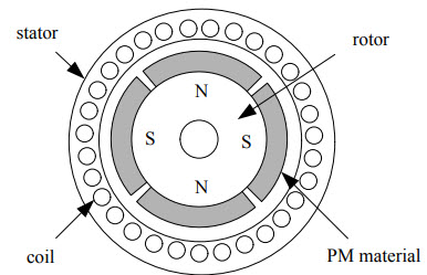
As you can see in the image, a BLDC motor consists of two main parts: a stator and a rotor.
Stator:
The structure of the stator of a BLDC motor is similar to that of an induction motor. It is made up of stacked steel laminations with axially cut slots for winding. The winding in BLDC is slightly different than that of the traditional induction motor.
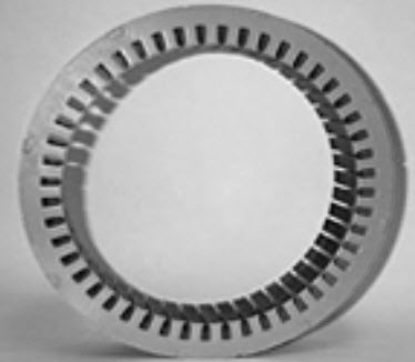
Generally, most BLDC motors consist of three stator windings that are connected in star or ‘Y’ fashion (without a neutral point). Additionally, based on the coil interconnections, the stator windings are further divided into Trapezoidal and Sinusoidal Motors.
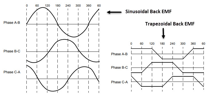
In a trapezoidal motor, both the drive current and the back EMF are in the shape of a trapezoid (sinusoidal shape in case of sinusoidal motors). Usually, 48 V (or less) rated motors are used in automotive and robotics (hybrid cars and robotic arms).
Rotor:
The rotor part of the BLDC Motor is made up of permanent magnets (usually, rare earth alloy magnets like Neodymium (Nd), Samarium Cobalt (SmCo), an alloy of Neodymium, Ferrite, and Boron (NdFeB)).
Based on the application, the number of poles can vary between two and eight with North (N) and South (S) poles placed alternately. The following image shows three different arrangements of the poles. In the first case, the magnets are placed on the outer periphery of the rotor.
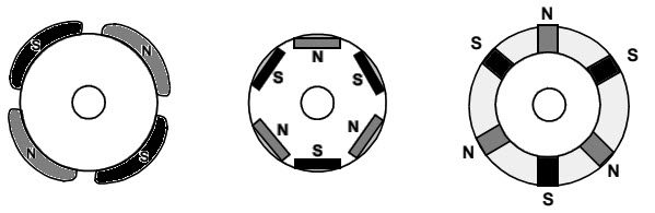
The second configuration is called a magnetic-embedded rotor, where rectangular permanent magnets are embedded into the core of the rotor. In the third case, the magnets are inserted into the iron core of the rotor.
Position Sensors (Hall Sensors):
Since there are no brushes in a BLDC Motor, the commutation is controlled electronically. In order to rotate the motor, the windings of the stator must be energized in a sequence and the position of the rotor (i.e. the North and South poles of the rotor) must be known to precisely energize a particular set of stator windings.
A Position Sensor, which is usually a Hall Sensor (that works on the principle of Hall Effect) is generally used to detect the position of the rotor and transform it into an electrical signal. Most BLDC Motors use three Hall Sensors that are embedded into the stator to sense the rotor’s position.
The output of the Hall Sensor will be either HIGH or LOW depending on whether the North or South pole of the rotor passes near it. By combining the results from the three sensors, the exact sequence of energizing can be determined.
Working Principle:
BLDC motor works on the principle similar to that of a conventional DC motor, i.e., the Lorentz force law which states that whenever a current-carrying conductor placed in a magnetic field it experiences a force. As a consequence of the reaction force, the magnet will experience an equal and opposite force. In case BLDC motor, the current-carrying conductor is stationary while the permanent magnet moves.
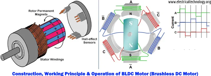
When the stator coils are electrically switched by a supply source, it becomes an electromagnet and starts producing the uniform field in the air gap. Though the source of supply is DC, switching makes to generate an AC voltage waveform with trapezoidal shape. Due to the force of interaction between the electromagnet stator and the permanent magnet rotor, the rotor continues to rotate.
Consider the following setup of three windings in the stator designated A, B, and C. For the sake of understanding, let us replace the rotor with a single magnet.
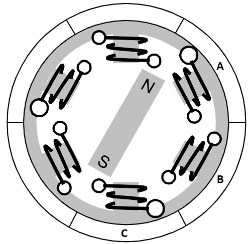
We know that when a current is applied through a coil, a magnetic field is generated and the orientation of the field lines i.e. the poles of the generated magnet will depend on the direction of the current flowing through the coil.
Using this principle, if we supply current to the coil A it will generate a magnetic field and attract the rotor magnet. The position of the rotor magnet will shift slightly clockwise and will align with A.
If we now pass current through coils B and C one after the other (in that order), the rotor magnet will rotate in the clockwise direction.
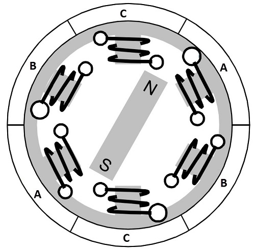
To increase efficiency, we can wind the opposite coils using a single coil so that we get the double attraction. Further increasing the efficiency, we can energize two coils at the same time so that one coil will attract the magnet and the other coil will repel it. During this time, the third will be idle.
For a complete 3600 rotation of the rotor magnet, six possible combinations of the coils A, B, and C are applicable and are shown in the following timing diagram.
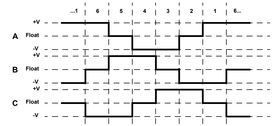
Based on the above diagram, we can confirm that at any time, one phase is positive, one phase is negative and the third phase is idle (or floating). So, based on the inputs from the Hall Sensors, we have two switches in the phases as per the above diagram.
Driving Brushless DC Motors:
If stator and rotor are essential parts of a BLDC Motor that are integral to it, then the driving electronics are equally essential. A Block diagram of a typical Brushless DC Motor control or drive system is shown in the following image.
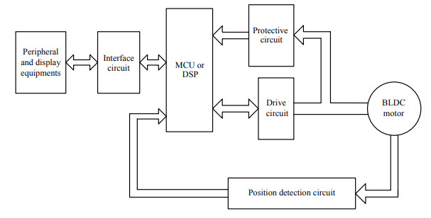
This drive circuitry is often known as Electronic Speed Controller System or simply an ESC. One common setup is called the Full-Bridge Drive Circuit. It consists of an MCU with PWM outputs, six MOSFETS for the three phases of the stator windings, feedback from the Hall sensors, and some power supply-related components.
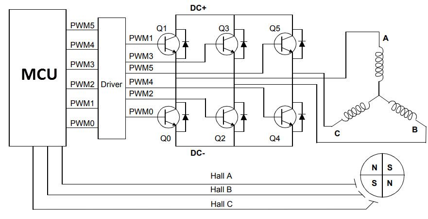
The MCU can be programmed to appropriately switch the MOSFETS based on the data from the Hall Sensors.
Advantages of BLDC Motors:
Since BLDC Motors are electronically commutated, there are several advantages over traditional Brushed DC Motors. Some of them are:
- It has no mechanical commutator and associated problems
- High efficiency due to the use of permanent magnet rotor
- High speed of operation even in loaded and unloaded conditions due to the absence of brushes that limits the speed
- Smaller motor geometry and lighter in weight than both brushed type DC and induction AC motors
- Long-life as no inspection and maintenance is required for commutator system
- Higher dynamic response due to low inertia and carrying windings in the stator
- Less electromagnetic interference
- Quiet operation (or low noise) due to absence of brushes
Disadvantages of Brushless Motor:
- These motors are costly
- The electronic controller required to control this motor is expensive
- Not much availability of many integrated electronic control solutions, especially for tiny BLDC motors
- Requires complex drive circuitry
- Need of additional sensors
Applications of Brushless DC Motors (BLDC):
Brushless DC Motors (BLDC) are used for a wide variety of application requirements such as varying loads, constant loads, and positioning applications in the fields of industrial control, automotive, aviation, automation systems, health care equipment, etc. Some specific applications of BLDC motors are
- Computer hard drives and DVD/CD players
- Electric vehicles, hybrid vehicles, and electric bicycles
- Industrial robots, CNC machine tools, and simple belt-driven systems
- Washing machines, compressors, and dryers
- Fans, pumps, and blowers
Conclusion:
- MATLAB demo model named ‘Speed control of a DC motor using BJT H-bridge’ is studied.
- Commented on the armature current shoot-up from the scope results.
- The Four-Quadrant Chopper DC Drive (DC7) block is also studied and compared with the H-bridge model.
- A 2-quadrant chopper is developed using Simulink & explained the working of the same with the relevant results.
- The operation of BLDC motor is studied.