Planetary Gear
"Motion analysis of Planetary Gear Mechanism using Solidworks".
1. Aim: TO ANALYSE THE MOTION ANALYSIS OF A PLANETARY GEAR MECHANISM USING SOLIDWORKS.
2. Objective:
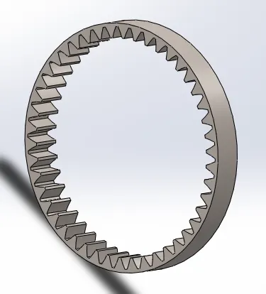
- To create an internal ring with the following properties:
Module = 2.5 (ANSI METRIC must be used while selecting Gear train).
Number of teeth = 46
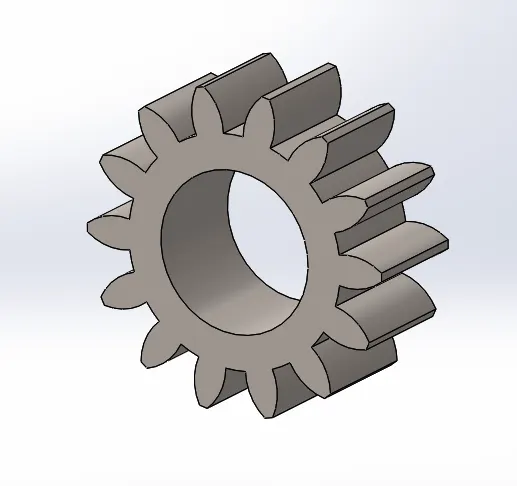
- To create sun gear with the following properties:
Sun Gear
Number of teeth = 14
- Input Speed of the Gear = 200 rpm.
Number of Planet gears = 4
The carrier must be designed based on the other components (considering safe design).
- Finally, after designing the Solidworks Model with the above parameters, we are going to run a simulation on the following cases.
| Sl.No | Input | Output | Fixed |
| 1 | Sun Gear | Carrier | Ring Gear |
| 2 | Ring Gear | Carrier | Sun Gear |
| 3 | Sun Gear | Ring Gear | Carrier |
3. Overview:
An epicyclic gear train (also known as planetary gear) consists of two gears mounted so that the center of one gear revolves around the center of the other. A carrier connects the centers of the two gears and rotates to carry one gear, called the planet gear or planet pinion, around the other, called the sun gear or sun wheel. The planet and sun gears mesh so that their pitch circles roll without slip. A point on the pitch circle of the planet gear traces an epicycloid curve. In this simplified case, the sun gear is fixed and the planetary gear(s) roll around the sun gear.
An epicyclic gear train can be assembled so the planet gear rolls on the inside of the pitch circle of a fixed, outer gear ring, or ring gear, sometimes called an annular gear. In this case, the curve traced by a point on the pitch circle of the planet is a hypocycloid.
The combination of epicycle gear trains with a planet engaging both a sun gear and a ring gear is called a planetary gear train.Epicyclic gears get their name from their earliest application, which was the modelling of the movements of the planets in the heavens. Believing the planets, as everything in the heavens, to be perfect, they could only travel in perfect circles, but their motions as viewed from Earth could not be reconciled with circular motion
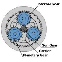
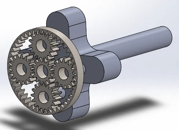
Fig 1. Planetary Gear Mechanism
4. Calculation:
The module(m) is the ratio of pitch circle diameter to the number of teeth.
so, module(m) = pitch circle diameter(d)/no. of teeth(T)
For Ring Gear:-
Module(m) = 2.5
No. of Teeth(T) = 46
So, Pitch circle Diameter(d) = m*T = 2.5*46 = 115
For Sun Gear:-
Module(m) = 2.5
No. of Teeth(T) = 14
So, Pitch Circle Diameter(d) = m*T = 2.5*14 = 35
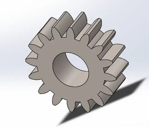
For Planet Gear:-
Module(m) = 2.5
No. of Teeth(T) =?
No. of teeth of Ring Gear = No. of teeth of Sun Gear + 2*No. of teeth of Planet Gear
So, No. of teeth of Planet Gear = (No. of teeth of Ring Gear - No. of teeth of Sun Gear)/2
= (46-14)/2
=16
Pitch Circle Diameter(d) = 2.5*16
= 40
5. 3D Models of different types of Gears and Carrier:
1. Ring Gear:-
2. Sun Gear:-
3.Planet Gear:-
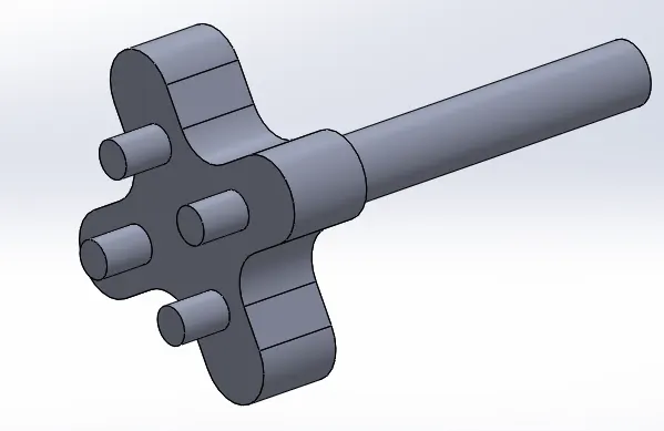
4.Carrier:-
5. Assembly:-
6. Study different types of casses for Motion analysis of Planetary Gear:
Case 1:-
- In this case at first we have to put the motor at the axis of Sun gear and have to put the input gear speed to 200 rpm.
- After that we have to make contact between the parts(Sun gear,Planet gear and Carrier).
- At last we have to fix the Ring gear and have to do the motion analysis so that we can get the output plot.
Case 2:-
- In this case at first we have to put the motor at the axis of Ring gear and have to put the input gear speed to 200 rpm.
- After that we have to make contact between the parts(Ring gear, Planet gear and Carrier).
- At last we have to fix the Sun gear and have to do the motion analysis so that we can get the output plot.
Case 3:-
- In this case at first we have to put the motor at the axis of Sun gear and have to put the input gear speed to 200 rpm.
- After that we have to make contact between the parts(Ring gear, Sun gear and Planet gear).
- At last we have to fix the Carrier and have to do the motion analysis so that we can get the out plot.
7. Results:
Case 1: Fixing the Ring Gear, giving input to the sun gear and receiving output at the carrier:-
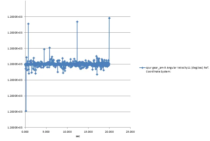
Input
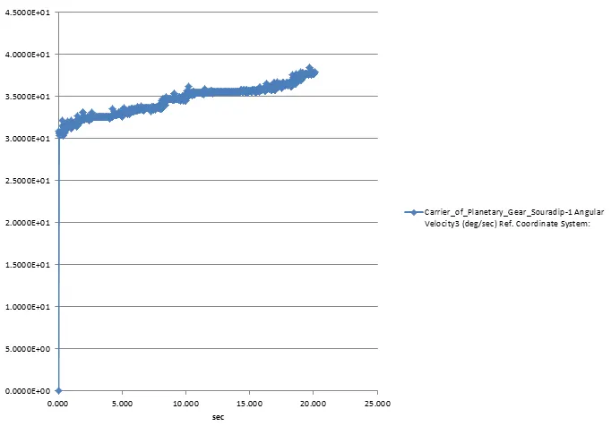
Output
Animation:
Case 2: Fixing the Sun gear, giving input to the Ring gear and receiving output at the carrier:-
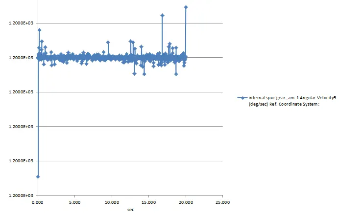
Input
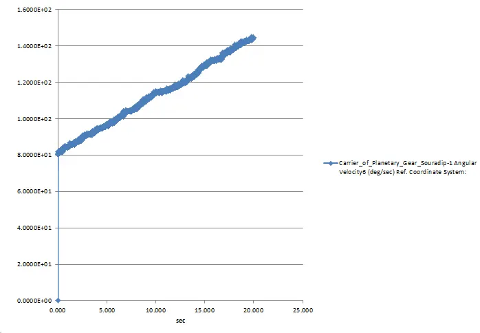
Output
Animation:
Case 3: Fixing the carrier, giving input to the Sun gear and receiving output at the Ring gear:-
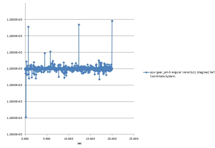
Input
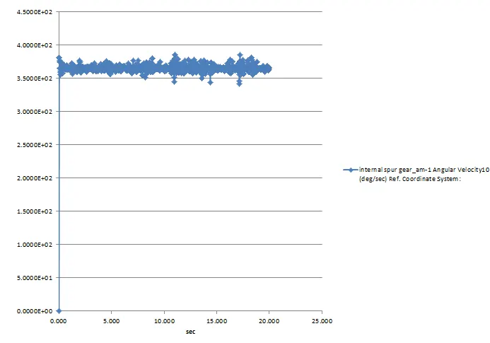
Output
Animation:
8. Conclusion:
The motion analysis of Planetary gear mechanism has performed for different casses so that we can get the different types of output plot .
9. Reference:
1. https://en.wikipedia.org/wiki/Epicyclic_gearing
2. https://www.apexdyna.nl/en/planetary-gearbox-introduction/