MBD Simulation on a Piston Assembly
"Motion analysis of Piston Assembly using Solidworks".
1. Aim: TO ANALYSE THE MOTION ANALYSIS OF PISTON ASSEMBLY USING SOLIDWORKS.
2. Overview:
A slider-crank linkage is a four-link mechanism with three revolute joints and one prismatic, or sliding, joint. The rotation of the crank drives the linear movement of the slider, or the expansion of gases against a sliding piston in a cylinder can drive the rotation of the crank.
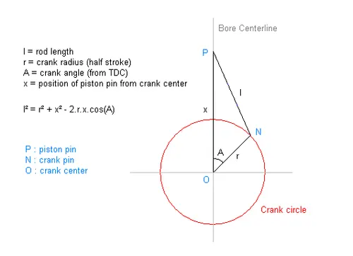
There are two types of slider-cranks: in-line and offset.
- In-line: An in-line slider-crank has its slider positioned so the line of travel of the hinged joint of the slider passes through the base joint of the crank. This creates a symmetric slider movement back and forth as the crank rotates.
- Offset: If the line of travel of the hinged joint of the slider does not pass through the base pivot of the crank, the slider movement is not symmetric. It moves faster in one direction than the other. This is called a Quick-Return Mechanism.
Wrist Pin Offset - The position of the Wrist Pin is going to be varied as followed, but the center of the axis of the Piston Head and the Crank are coincident to each other i.e. they are on the same plane in all three cases.
3. Objective:
Our main objective is to do the motion analysis of piston assembly by modeling all the parts and then assemble them in Solidworks. The motion analysis is going to be carried out in three different conditions,
| Sl.No |
Wrist Pin Offset ` |
Crank Speed (Rpm) |
| 1 | "0" mm | 2000 |
| 2 | 10 mm Positive | 2000 |
| 3 | 10 mm Negative | 2000 |
4. Procedure:
Before going to do the motion analysis of piston assembly at first we need to design all the parts individually and assemble them in Solidworks.
- Piston design:-
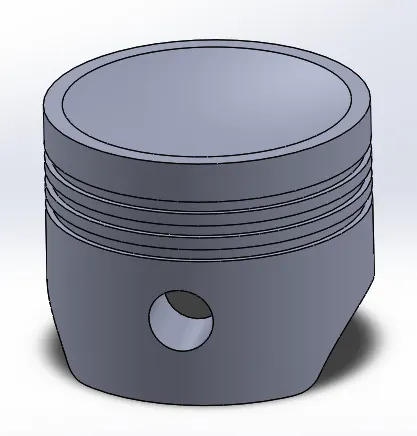
The piston is a component that is used in many machines and also transfers power from combusting fuel to the crank with the help of a connecting rod. To design the piston at first we have to do the 2D sketch with the aforementioned dimensions and zero offset and then make the 2D design into a 3D model by extrude option. The 3D model of Piston is given below.
- Wrist Pin:-
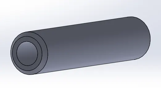
The wrist pin is used to connect the connecting rod and piston for transferring powers. To design the wrist pin at first we have to do a 2D sketch with the aforementioned dimensions and then make the 2D sketch into a 3D model by using extrude option. The 3D model of Wrist Pin is given below.
- Connecting Rod:-
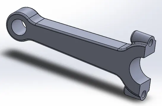
The connecting rod connects one side piston with another side of the crank and also helps to convert the linear motion into rotational motion. To design the connecting rod at first we have to do the 2D sketch with the aforementioned dimensions and then make the 2D sketch into a 3D model by using extrude option. The 3D model of the connecting rod is given below.
- End Cap:-
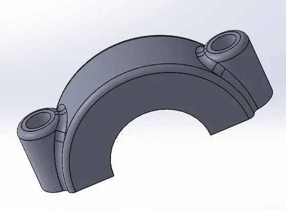
The End Cap is an extension of the connecting rod which helps to mount the connecting rod on the crank. To design the End Cap at first we have to do a 2D sketch with the aforementioned dimensions and then make the 2D sketch into a 3D model by using extrude option. The 3D model of the End Cap is given below.
- Crank:-
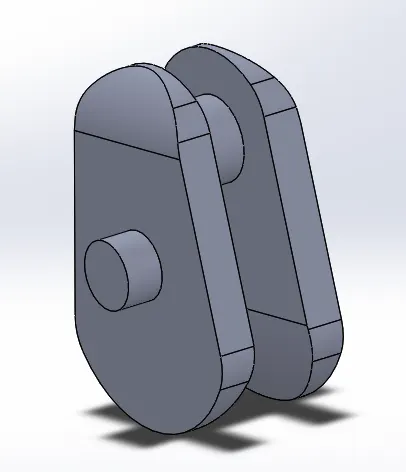
A crank can be used to convert circular motion into reciprocating motion, or conversely turn reciprocating motion into circular motion. To design the crank at first we have to do a 2D sketch with the aforementioned dimensions and then make the 2D sketch into a 3D model by using extrude option. The 3D model of Crank is given below.
- Assembly:-
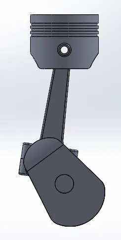
To do the assembly at first we have to import the Crank which is used as a basis for our assembly. After that, we have to use the mate option to align the Crank properly. Similarly, we have to import the other parts and then assemble them by using the mate option. The assembly of Piston is given below.
5. Simulation and Analysis:
In this study, we are going to offset the wrist pin in three different ways and analyze its effect on the linear displacement of the piston.
- To do the motion analysis in all three cases at first we have to put a motor as an input with 2000 rpm at the crank axis.
- Similarly, we have to use 12000 frames per second and also have to use precise contact to get more accurate results.
- After that, we have to make contact between different types of parts of the piston assembly.
- At last, we have to enable the gravity along the y-axis and initiate the calculation process of the motion analysis.
- Study 1(0 mm Offset):-
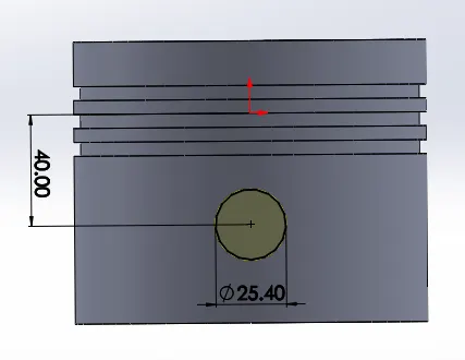
In this study, the Wrist pin and the Rotational axis of the Crank coincides with each other.
Geometry:-
Plot Output:-
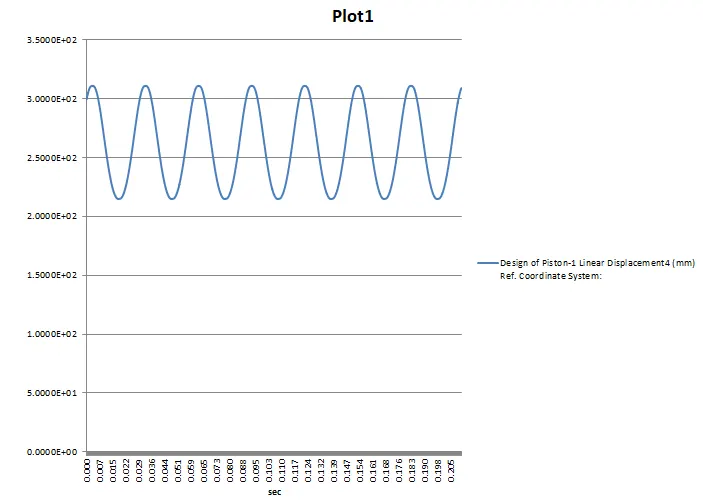
In the above plot, we can see that the linear displacement of the piston starts between approx 2.2000E+02 and 3.1000E+02. The smooth constant curve indicates that the constant linear displacement of piston w.r.t time.
- Study 2(10 mm positive offset):-
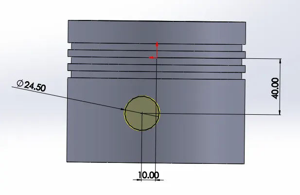
In this study, the Wrist pin and the Rotational axis of the Crank coincides with each other with a 10 mm positive offset.
Geometry:-
Plot Output:-
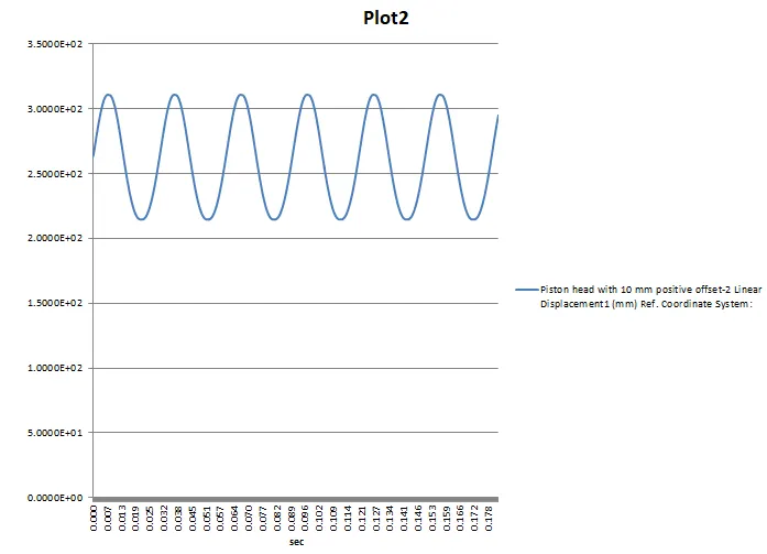
The above plot depicts the slight difference in the extreme positions of the Piston due to the non-linearity of the Wrist Pin and Crank axis. The smooth constant curve indicates that the constant linear displacement of piston w.r.t time similar to the previous plot of study 1.
- Study 3(10 mm negative offset):-
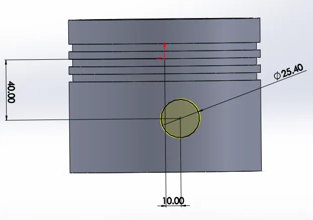
In this study, the Wrist pin and the Rotational axis of the Crank coincides with each other with a 10 mm negative offset.
Geometry:-
Plot Output:-
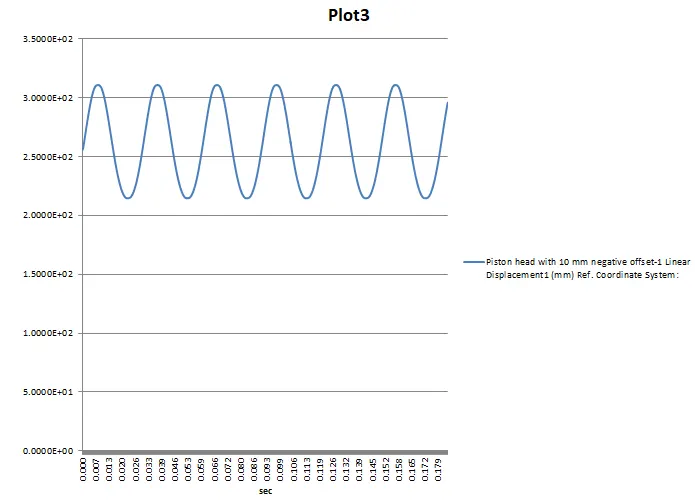
The above plot shows similar characteristics to that of a positive Wrist Pin Offset. The smooth constant curve indicates that the constant linear displacement of piston w.r.t time. but the difference exists in the crank angle.
6. Result:
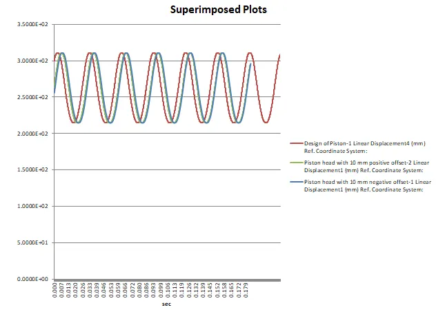
From the above three studies, we get approx the same plot for all. For comparing the results of all the three plots of different motion analysis, we are using a superimposed graph. The superimposed graph of all the above three plots is given below.
7. Conclusion:
The motion analysis of piston assembly with three different cases has performed. In all the above three plots of different cases, we can see that the linear displacement of the piston is nearly the same in all the cases but the starting position, as well as the path at some duration, is different for each study which is due to the 10 mm positive and negative offset provided in the second and third study. Providing Offset offers much less resistance leading to more engine power and speed.
Link to Solidworks Parts and Assembly:
https://drive.google.com/drive/folders/1HkwtjigAU2yCWyuUCcDd1ESu-vdNtoUi?usp=sharing