Week-7 Challenge: DC Motor Control
1A. Speed Control of DC Motor using BJT - H bridge:
The mathematical model is given by
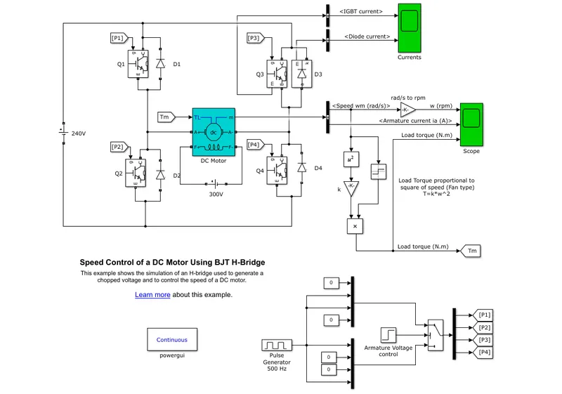
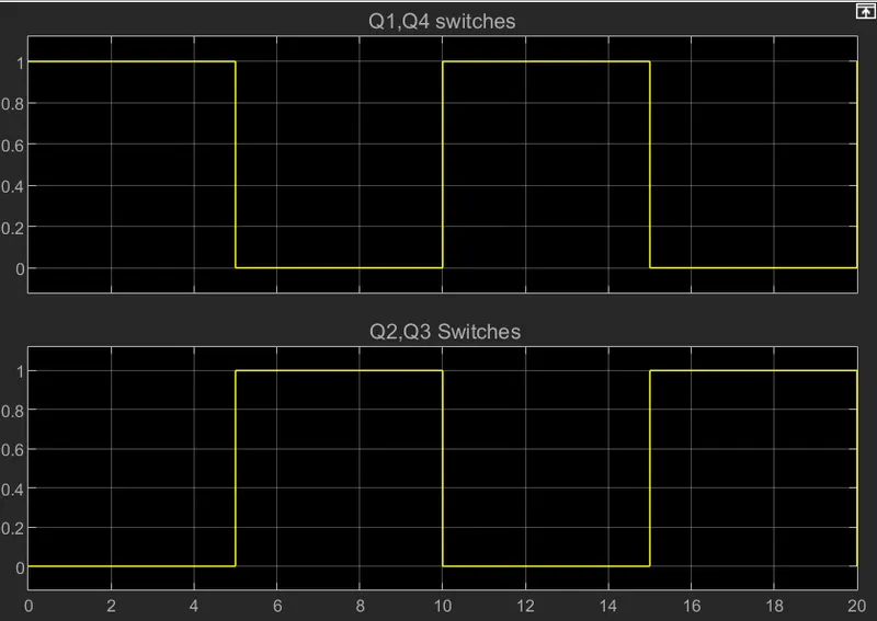
Speed Control of DC motor using BJT - H bridge has a two-quadrant operation. It consists of 4 Power electronic switches Q1 Q2 Q3 Q4. Each leg has two switches and there are two such legs. Only one switch should be turned ON in one leg to avoid short circuit conditions which lead to failure of the system. A DC supply is given to the circuit. For a duration of T1 switches, Q1 and Q4 are turned ON. Current flows from a positive terminal to Q1 through the load-connected DC motor to Q4 and back to the negative terminal. The forward motoring operation occurs. Similarly when switch Q2 and Q3 is turned ON the current flows in the negative direction through the load making it a reverse motoring operation. the same can be observed from the scope.
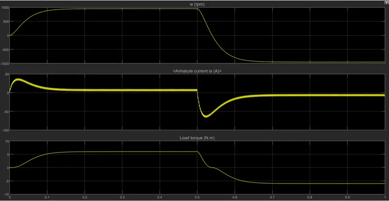
1B. Due to the sudden change in the direction of rotation of the motor, there is a transient current that occurs which causes the shoot up at T=0 and T=0.5 at the point of reversal of current flow.
1C. DC7 Four quadrant Chopper
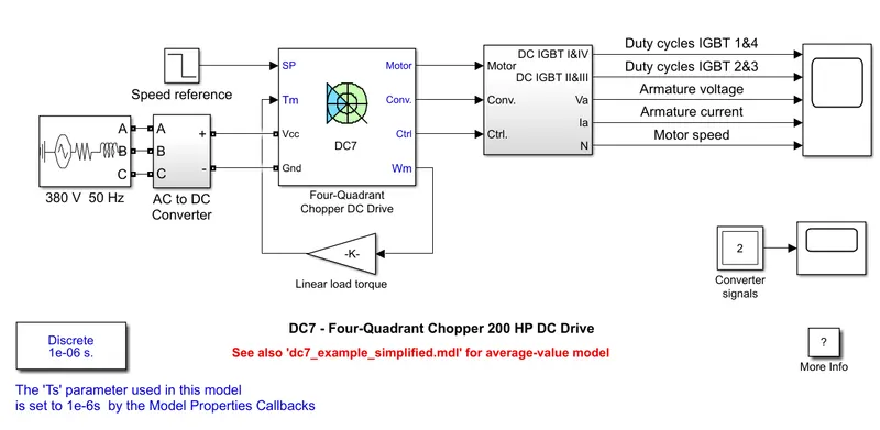
Four quadrant chopper has four operations, Forward motoring, forward braking, reverse motoring, and reverse braking. The subsystem Four Quadrant Chopper DC Drive does this work The block works with a reference speed given to it and tries to achieve the speed at every given instant of time. The Actual speed is taken as feedback which is converted to torque. A supply from the mains is converted to DC voltage with AC-DC Converter. Various outputs can be observed from the scope.
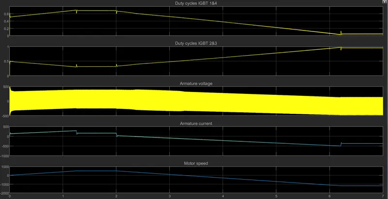
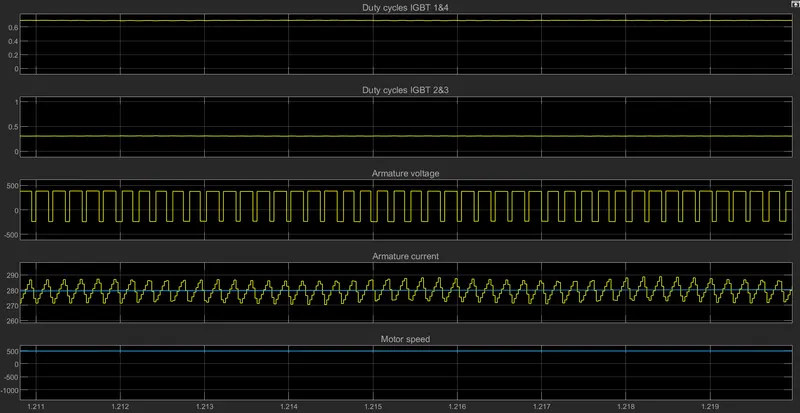
It can be seen that the armature voltage varies with the reference speed. When switches 1 and 4 is ON, 2 and 3 is off and vice versa.
2. Two Quadrant Operation
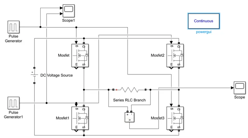
The gate signals are given such that switches Q1 and Q4 is turned ON at a time and Q2 and Q3 are turned ON simultaneously.
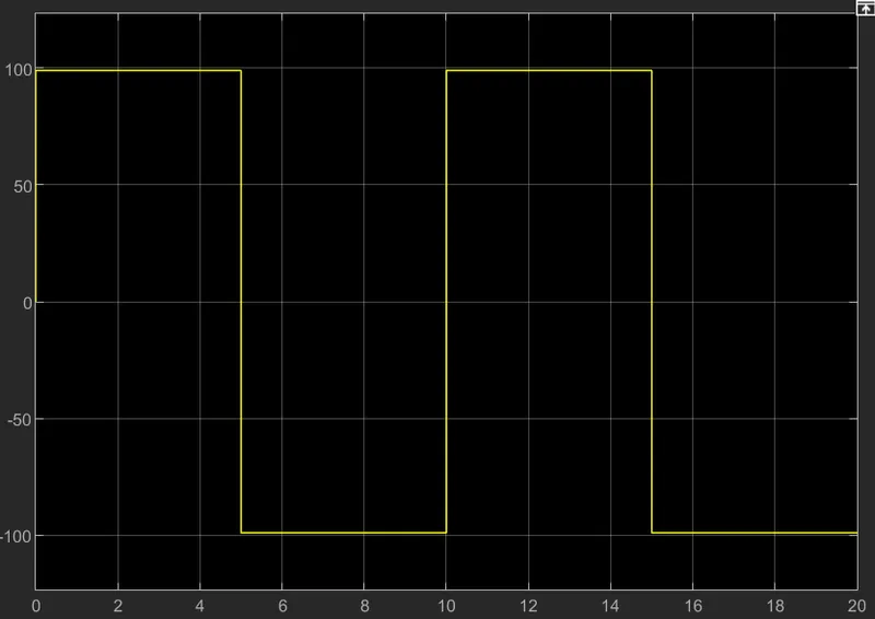
The output of the chopper
3. Working of the BLDC motor.
BLDC motors are also called electronically commutated motors.
Motors operate based on a similar principle, in which the rotational motion is generated through the attraction and repulsion of magnetic poles of permanent and electromagnets. However, the way these motors are controlled is very different. BLDCs require a complex controller to convert a single DC power to a three-phase voltage, whereas a brushed motor can be controlled by regulating the DC voltage.
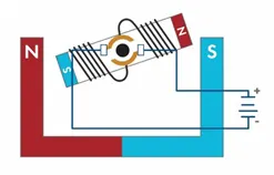
A BLDC motor is a kind of flipped version of a brushed motor because the permanent magnets are installed in the rotor, whereas the coil windings become the stator.
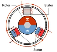
There are motors with different magnet arrangements where the stator may have different numbers of windings and the rotor may have multiple pole pairs as shown in the figure.
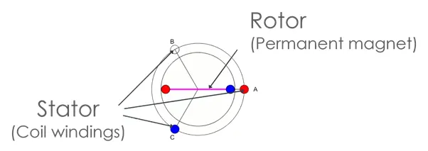
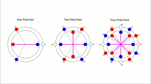
In the beginning, none of the coils are energized and the rotor is stationary. Applying a voltage across two phases, A and C generates a combined magnetic field along the axis running through A and B. As a result, the rotor starts to turn to align itself with the stator magnetic field.
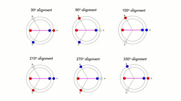
This means that if the correct phases are commutated every 60 degrees. More pole pairs can be added to such machines, requiring the commutation to take place more often. To properly commutate the motor at the right times with the correct phases, the controller needs to know the exact position of the rotor at any time, which is usually measured by using Hall sensors.
In a 1 pole pair system, once the rotor completes 60 degrees of rotation, the next commutation (pole change) occurs. it becomes clear that commutation occurs in such a way that the rotor never aligns with the stator magnetic field but is always chasing it.
There are two reasons for switching phases in BLDC motors in exactly this way. First, if the rotor and stator magnetic fields were allowed to align perfectly the motor would create zero torque, which is unfavorable. Second, maximum torque occurs when the fields are 90 degrees to each other. The goal, therefore, is to bring this angle close to 90 degrees.