Week -2
1. Simulink model of doorbell using a solenoid block.
In this problem statement, a solenoid has to be connected in series with a switch that is connected to a supply. The switch closes every 2 secs and opens after 2 secs. When the switch closes for 2 secs the solenoid is energized and pulls the plunger of the bell to create a sound.
The Simulink model for the same is as shown in fig1.
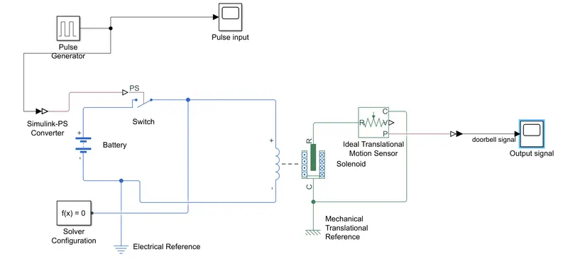
Fig1: Simulink Model to energize the solenoid.
Here, A 12V battery is connected in series with a switch that is connected in series with the solenoid. A pulse generator gives the input signal to turn ON the switch. When the switch is ON the solenoid gets energized and the plunger moves from R towards C port. An ideal translational sensor measures the linear motion of the plunger which is plotted in the output scope. Electrical and mechanical references are provided on both sides respectively to have a common reference. A solver configuration block is added to run the model.
To keep the switch ON for 2 secs a pulse wave of time period 4 secs and a duty cycle of 50% is given as the input to the signal terminal of the switch as shown in fig2. A switch block works such that, as the physical signal value is greater than the threshold value then the switch is closed else it is open. In this model, the threshold value is equal to 0.5.
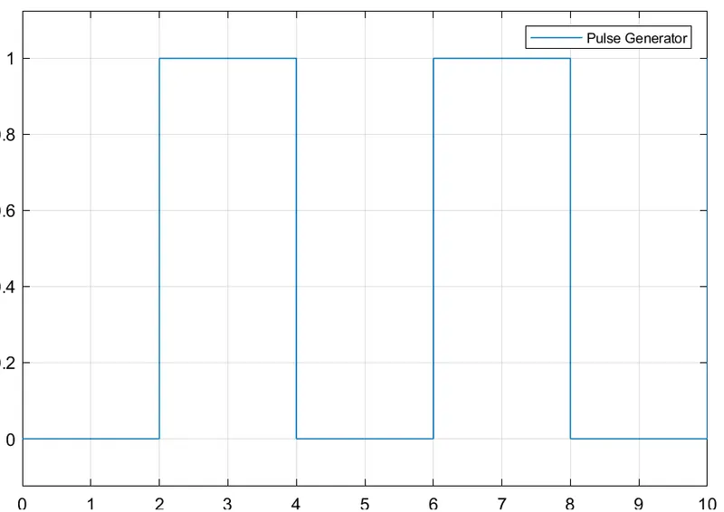
Fig2: Physical signal to the switch.
When the switch is turned ON, the solenoid gets energized due to which the plunger moves from R towards C. Hence a signal with vibration appears initially at every 2 secs which later settles down at the end of 2 secs which is measured by an ideal translational motion sensor. The doorbell signal is plotted in fig3.
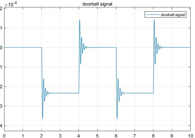
FIg3: Signal at the plunger of the solenoid.
Therefore it can be seen that when the switch is closed for every 2 secs the plunger moves forward and backward which causes the doorbell to ring every 2 secs. A Matlab Simulink file is attached for reference.
2. Thermistor to sense the temperature of a heater & turn on or turn off the fan.
In this problem statement, a thermister is required to sense the temperature of the thermal source and a fan should turn ON or OFF based on the given condition.
The temperature source is heated as shown in Table1.
|
Temperature (in degrees) |
Time Duration (in secs) |
| 20 | 0-10 |
| 27 | 10-30 |
| 23 | 30-50 |
Table1: Condition of temperature source.
Fan conditions: ON if the temperature is above 25 °C, OFF otherwise.
A thermistor is a resistor whose value of resistance depends on the temperature. Thermister simply refers to thermal + resistor. In this model as shown in fig4, a thermistor is used to react when there is a change in the temperature.
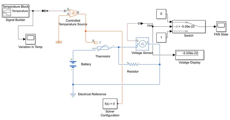
Fig4: To turn ON or OFF the fan due to change in temperature.
From the Simulink model, it can be seen that a controlled temperature source is used to hold the temperature according to the given condition. A signal builder block is used to plot a signal according to the given condition. The input signal for the controlled temperature block is as shown in fig5.
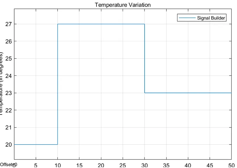
Fig5: Variation in temperature at controlled temperature source.
It can be seen from fig5 that, temp remains 20 degrees between 0-10secs, later increases to 27 degrees between 10-30 secs, and comes down to 23 degrees between 30-50 secs.
The output of the controlled temperature source block is connected to a thermistor. The electrical part of the thermistor is connected to a battery source of 12V and is connected in series with a resistor to limit the current. A voltage sensor is placed across the resistor to measure the voltage drop across it. An electrical and thermal reference is added in order to keep the system stable. A solver configuration block is added to run the model.
For the fan to turn ON and OFF according to the given condition( that is a fan should be ON when the temperature is equal to or greater than 25 degrees and should be OFF when the temperature is below 25 degrees) a switch is used to work accordingly. The voltage drop across the thermistor is measured and displayed. When the voltage is greater than 5.06e-22 then the fan state should be high else the fan state should be low. This is accomplished with the help of a switch and the fan state output is displayed in the scope. 5.06e-22 voltage is analogous to 25-degree temperature. The fan state is represented in fig6.
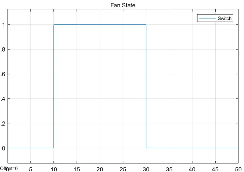
Fig6: State of the fan under the specified condition
Hence it can be seen from the result that, the fan is turned ON when the temperature rises about 25 degrees and turned OFF when the temperature is less than 25 degrees.
The Matlab Simulink file is attached for reference.