Week - 4
- Implementation of washing machine process using MATLAB Stateflow.
A washing machine is an appliance that is used for washing clothes on a day-to-day basis. The washing machine begins when a proper power supply and water supply are given.
The conditions given for working of the washing machine is stated in table 1
|
Sl No |
Process |
Time (secs) |
|
1. |
Soaking |
200 |
|
2. |
Washing |
100 |
|
3. |
Rinsing |
20 |
|
4. |
Drying |
50 |
With the fulfillment of proper power and water, all the above processes will work in a sequential loop and the process ends when the process is complete.
The Simulink Model for the above process is shown in fig1.
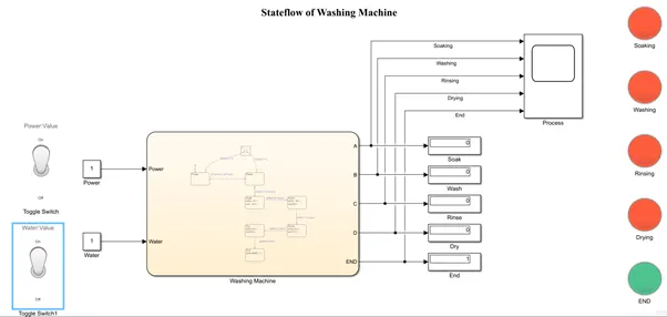
Fig1: Stateflow of washing machine.
It can be seen from the above figure, Power and Water supply are supplied by turning ON the toggle switch selected from the dashboard from Simulink Library. These values are given as input to the chart block. The process of washing the machine occurs inside the chart block as per the given conditions. The output of the chart is A, B, C, D, and END which represents Soaking, Washing, Rinsing, Drying, and END respectively which is shown in fig2. The process occurring in the Simulink is displayed in the display block with the value 1. Respective lamp block turns green when the process occurs for a given duration of time as per the condition.
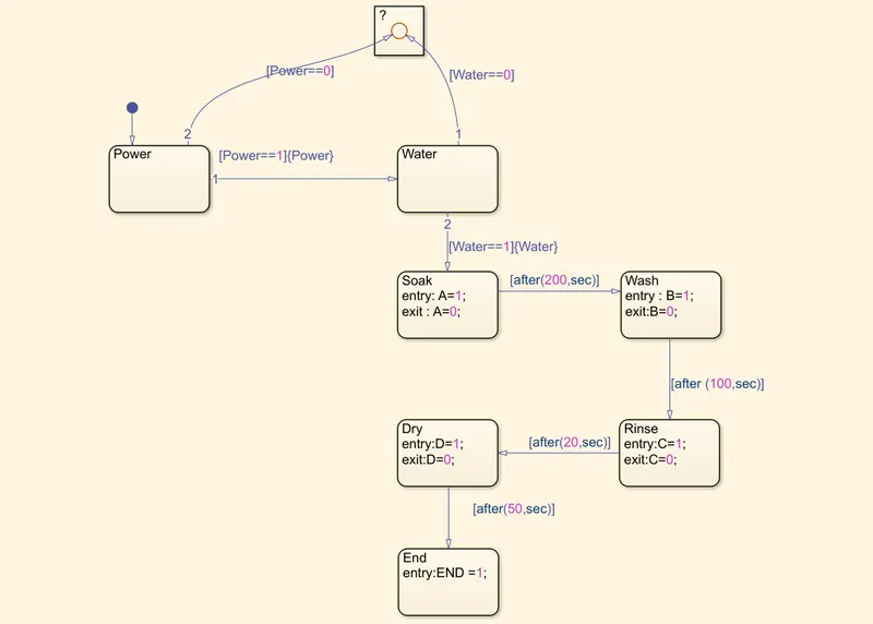
Fig2: Stateflow of washing machine.
As per the Stateflow, when power or water supply is not given then the process is terminated. When the power and water condition are satisfied, the process begins with soaking. After a delay of 200secs the process shifts to washing. Once 100 secs is completed, rinsing begins for 20secs and dries for 50 secs. After completion of this sequential loop, the process ends.
The Simulation is run for a simulation time of 420 secs to notice the working of the Stateflow.
The working time duration of all these processes is plotted in the scope as shown in fig 3-7.
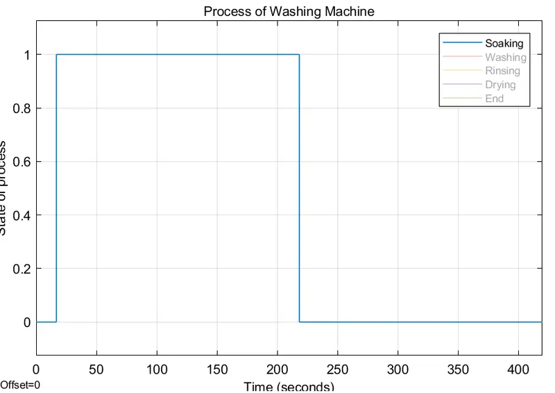
Fig 3: Soaking Process for 200secs.
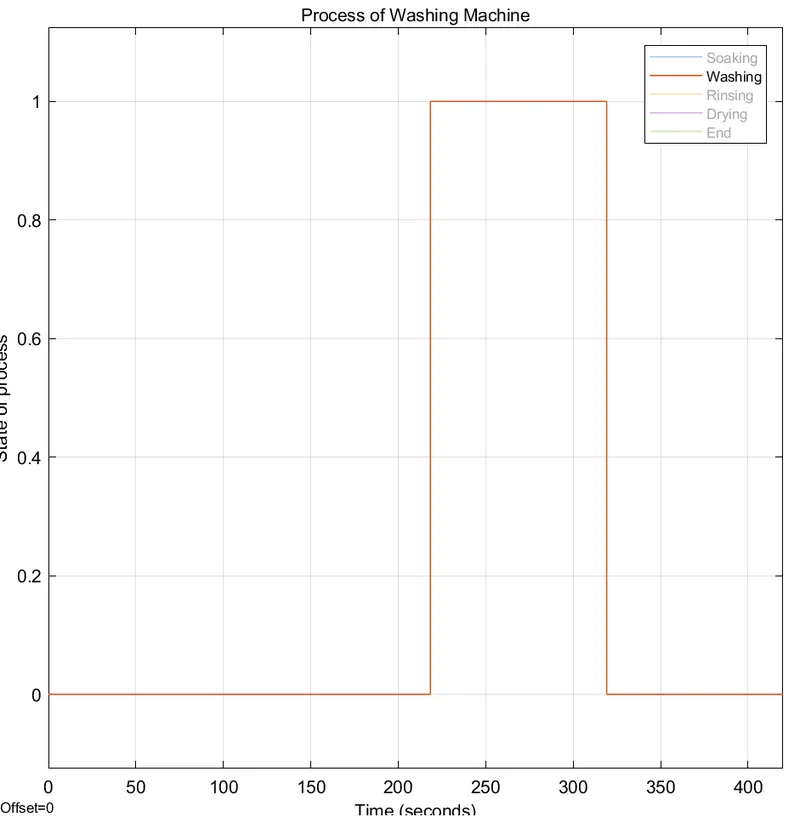
Fig 4: Washing Process for 100 secs.
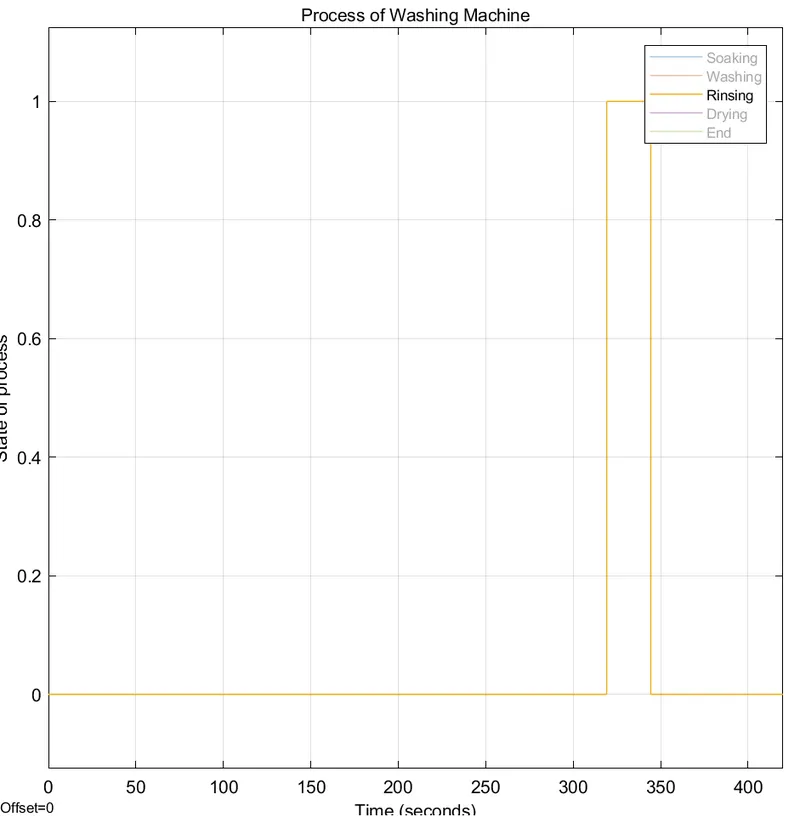
Fig 5: Rinsing Process for 20 secs.
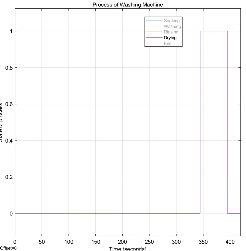
Fig 6: Drying Process for 50 secs.
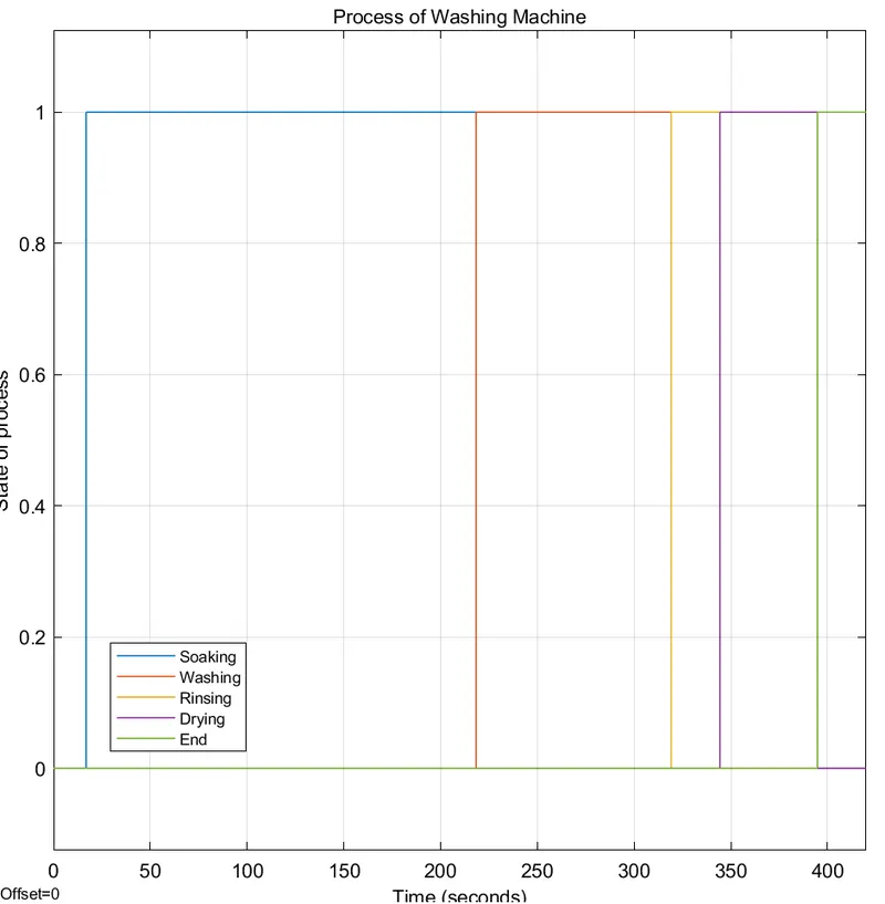
Fig 7: Overall Plot of Washing Machine Stateflow.
Therefore, with the given conditions the Stateflow for the washing machine is designed using MATLAB Simulink and analyzed with the help of scope.
The Simulink Model is attached for reference.
2. Implementation of Gear Shift using Simulink Chart.
Gear-shift is a Stateflow designed to shift gears proportional to the speed given by the driver. The conditions for Gear-shift are as given in Table1.
| Sl No | Speed (kmph) | Gear |
| 1. | 0-15 | 1 |
| 2. | 16-25 | 2 |
| 3. | 26-40 | 3 |
| 4. | 41-60 | 4 |
| 5. | Above 61 | 5 |
Table2: Conditions for Gear-shift.
To shift the gear according to the given speed conditions, a Simulink Model is created using Chart block from Simulink library as shown in fig8.
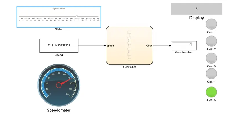
Fig 8 : Stateflow Diagram for Shifting gears with respect to speed.
It can be seen from the figure that, speed is connected as an input to the chart block. This speed is varied with the help of a slider selected from the dashboard. The speed range is between 0-100kmph. The speedometer shows the respective speed that is selected.The chart block contains the algorithm for a shift of gears as per the given condition as shown in fig 9. The selected gear number is displayed at the output of the chart block. Based on the displayed output i.e., the selected gear respective lamp is turned ON to show the selected gear proportional to the speed selected by the user.
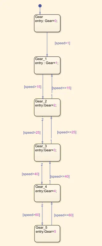
Fig 9: Stateflow algorithm for the gear shift.
The Simulink model is evaluated for all the cases and the output is observed.
Case 1: When speed is less than 15kmph.
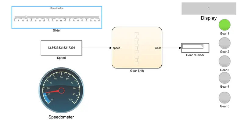
Fig 10: Gear 1 is selected.
Case 2: When speed is between 16kmph to 25kmph
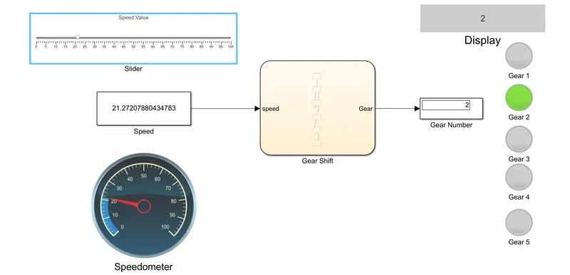
Fig 11: Gear 2 is selected.
Case 3: When speed is between 26kmph to 40kmph
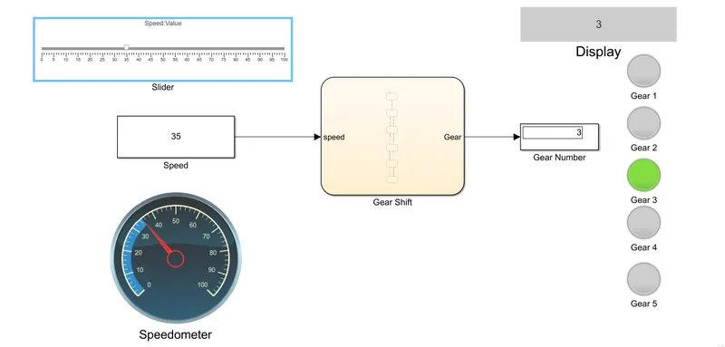
Fig 11: Gear 3 is selected.
Case 4: When speed is between 41kmph to 60kmph
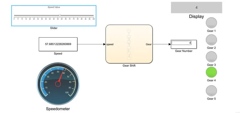
Fig 11: Gear 4 is selected.
Case 5: When speed is above 61kmph
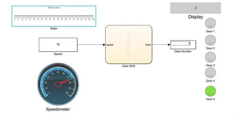
Fig 12: Gear 5 is selected.
Hence, from the above cases, it can be seen that the gear shifts with respect to change in speed as per the requirement with the designed Simulink Model.
The Simulink Model is attached for reference.