Week-7 Challenge: DC Motor Control
SOLUTION 1 : Speed Control of a DC Motor by using BJT
( A ) : The direction of rotation of a motor can be changed with the help of a H-Bridge BJT Circuit . The following figure shows the model of the Simulation :
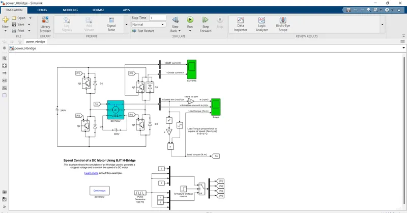
The model contains diodes, a DC Motor , BJTs etc.
H-bridge consists of 4 switches : Q1,Q2,Q3 and Q4 and also 4 Freewheeling diodes : D1,D2,D3 and D4
Here the swiches are BJTs , which are simulated by the IGBT Models.
There is a 240V DC Voltage source which is used here to give supply to the circuit.
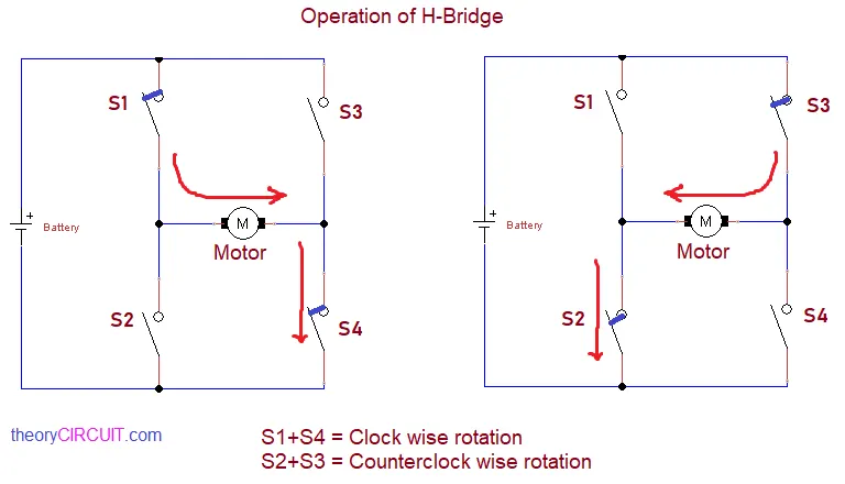
In the Forward motoring case of the motor ,i.e when Q1 & Q4 are turned on , a positive voltage is applied, so current flows from the battery to the Motor through Q1 and then flows through Q4 and completes the circuit .Diodes D2 & D3 acts as freewheeling diodes when switches Q1 & Q4 are switched off .
In the Reverse motoring case of the motor ,i.e when Q2 & Q3 are turned on , a negative voltage is applied current flows from the battery to the Motor through Q3 and then flows through the Q2 and completes the circuit ..Diodes D1 & D4 acts as freewheeling diodes when switchesQ2 & Q3 are switched off .
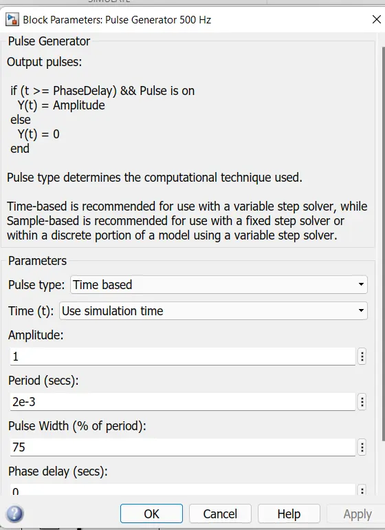
Motor starts in the positive direction. Since the pulse width given is 75 % , it supplies a voltage of 180V to the circuit .
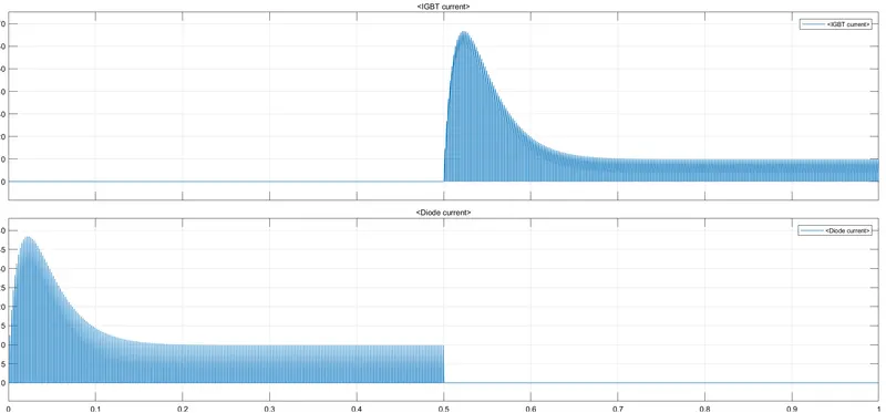
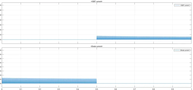
There are two scopes connected . The first scope displays the currents: The IGBT Current and the Diode Current .
The other scope is used to display the Speed , Armature Current and Load Torque .
( B ) At t = 0.5 seconds , it is evident that there is a speed change which is very huge reversal . This drastic reversal in the speed causes the Armature Current to shoot up , because of the transient behaviour of the system .
SCOPE 1 OUTPUT :
SCOPE 2 OUTPUT :
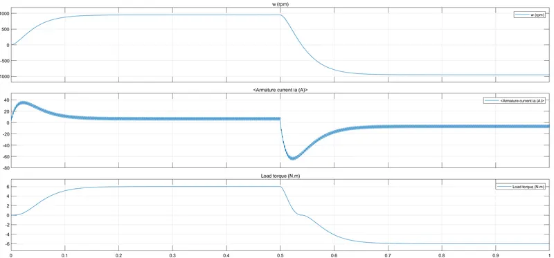
Here the armature current goes to a negative peak value of -65 A , which is not good for the system.
This behaviour of the shootup in the armature current can be improved by changing the pulse width and thus current shootup can be decreased .So we run the same with a pulse width of 40 %
MODIFIED SCOPE 1 OUTPUT :
SCOPE 2 OUTPUT :
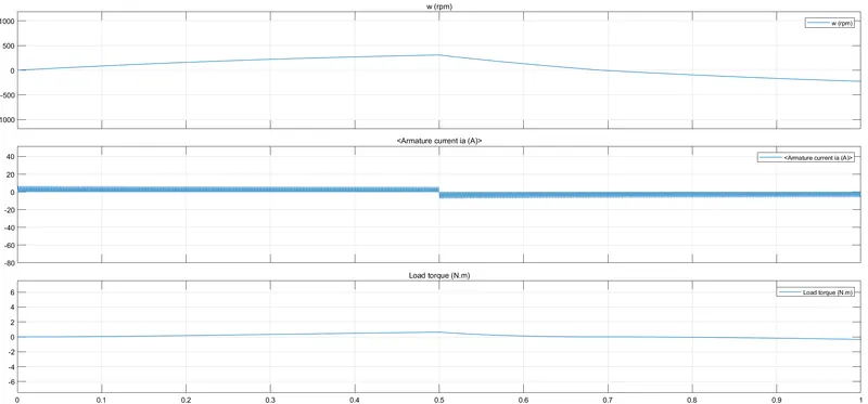
Now it is seen from the scope result that the armature current shootup has reduced to a very less value compared to the previous case.
( C ) The Four-Quadrant Chopper DC Drive (DC7) block compared with the H-bridge model.
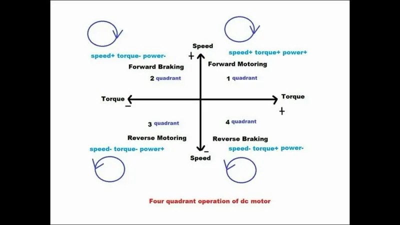
4 QUADRANT OPERATION IS AS SHOWN IN THE FIGURE :
A chopper is a DC -DC Converter .It is mainly used for motor control and regenerative braking also .
In the first quadrant when Speed and the torque is positive it will be Forward motoring.
In the second quadrant it is Forward braking when the Speed is positive but Torque is negative .
In the third quadrant when Speed and the torque is negative it will be reverse motoring
In the fourth quadrant it is reverse braking when the Speed is negative but Torque is positive .
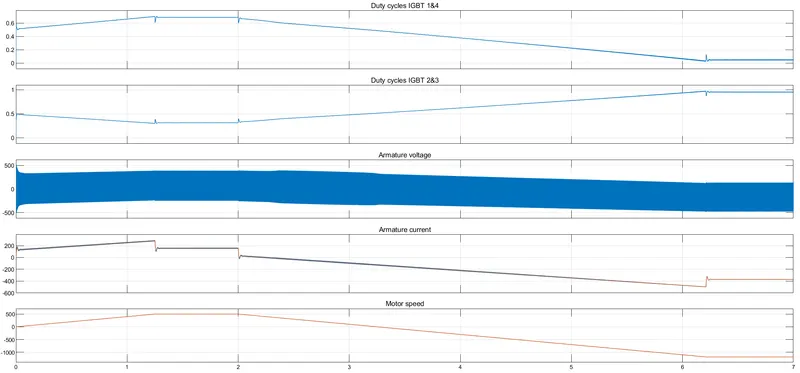
The 200 HP DC motor IN THIS MODEL is separately excited with a constant 150 V DC field voltage source. The armature voltage is provided by an IGBT converter controlled by two PI regulators. The converter is supplied by a 515 V DC bus obtained by rectification of a 380 V AC 50 Hz voltage source. In order to limit the DC bus voltage during dynamic braking mode, a braking chopper was added between the DC7 block and the diode rectifier.
The output of the Simulation :
On comparing both the models we understand that :
H Bridge Circuit :
( i ) Dynamic braking is possible but not Regenerative Braking
( ii ) If we change the polarity of the current then the direction of motor can be changed .
( iii ) Continuous values of current are obtained .
( iv ) Mainly used for controlling DC Motor speed and direction in Electro mechanical devices and Robotics applications .
4 QUADRANT CHOPPER Circuit :
( i ) Regenrative Braking is possible
( ii ) If we change the polarity of the current then the direction of motor cannot be changed .
( iii ) Discrete or chopped values of current are obtained
( iv ) Mainly used in automobiles to control the speed and direction of the motor.
SOLUTION 2 : We are asked to develop a 2-quadrant chopper using simulink.
The following figure is a two quadrant chopper :
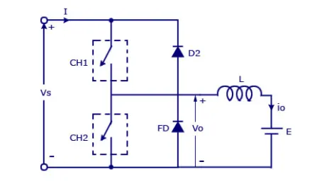
Here Vs is the DC Voltage source
CH1 & CH2 are the power electronic switches .
D2 & FD are the freewheeling diodes .
L is the inductive load
I is the current
io is the output current
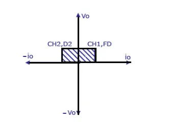
The 2 QUADRANT OPERATION :
The simulation of the 2 QUADRANT CHOPPER will be as shown in the below diagram
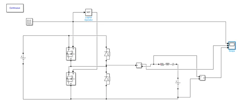
Here we have used
1. A pulse generator to provide the input pulse to the Switching devices ( Mosfet in this case )
2. Mosfet ( Acting as switch )
3. Diode
4. DC Voltage source
5. Current measurement block
6.Voltage measurement block
7. Series RLC Load
8. NOT logical operator
9. Scope
10. powergui block
The input from the pulse gate is given to the Gate of the Mosfet. We use a NOT Logical operator here so that we dont want both the Switching devices to operate at the same time . So when Mosfet 1 is ON , then with the help of Not operator we can turn the other Mosfet OFF. Then the DC Voltage source,two mosfets and the two diodes complete the circuit. Pulse width input is fed into the scope . Source current is fed to the current measurement block which then delivers it to the scope and also the series RLC LOAD.A Voltage measurement device is also used to measure the voltage across the load . Scope is used to display the output .
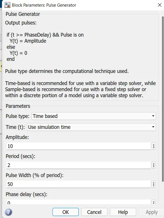
Pulse Generator parameters :
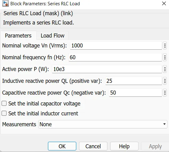
Series RLC Load values :
SCOPE OUTPUT :
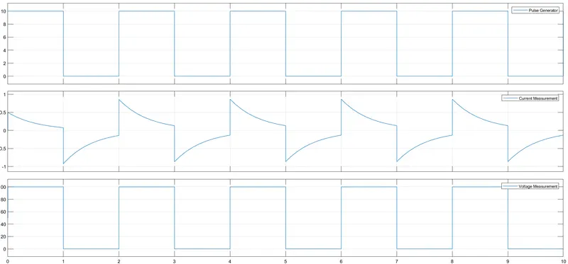
Here it can be seen that in the first half cycel , voltage and current both are positive . While in the other half cycle we can see that current is negative , but the voltage isnt , which is similar to the Two quadrant chopper , hence justified .
SOLUTION 3 : BLDC Motor
To make the operation more reliable , more efficient and less noisy , now the trend has evolved into usage of the Brushless DC Motors.BLDC Motors doesnt have brushes as the name suggests . Due to this it has very little maintenance . They provide the same power as compared to the Brush DC motors with more efficiency. They are electronically commutated type of motors . The rotor is a Permanent magnet and the stator of the BLDC will have a coil arrangement .When DC Power is applied to the coil , the coil becomes gets energized and it becomes an electromagnet . The operation of the BLDC Motor will be the result of the interaction between the Permanent magnet rotor and the Stator which has become an Electromagnet. The controlling of the BLDC Motor can be done by changing the magnitude and direction of the current which flows through the stator windings .
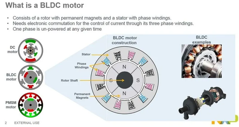
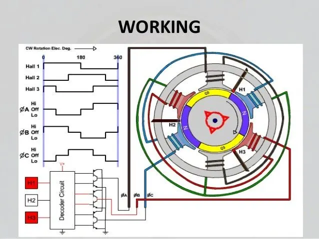
Stator of this BLDC Motor has 3 phase windings . The motor has a rotor position sensor which produce electrical sensors indicating the position of the rotor . Brushless Stator winding is driven from an electronic drive which is a 3 phase inverter . Hall sensors are used in the BLDC Motors.There is a sequence of excitation of the electromagnets which impses to the permanent magnet in angular movement which is always in the same direction and it will be mostly constant under the same excitation .The sequence of this will be in a cycle and the motor rotates until it is powered by the supply .
The sequence of excitation of the electromagnets inside the stator is such that the magnets of the motor are attracted to the electromagnets without ever reaching them . When electricity reaches coil 1 ,the opposite poles of the rotorand rotor are attracted to each other. When the rotor is getting close to the coil 1, the electricity flows in the coil 2. When the rotor is getting close to the coil 2 then electricity flows into coil 3 . Later when electricity flows through the coil 1 again , but this time with opposite polarity . This process is repeated continuously inside the engine of the motr thus ensuring rotation of the rotor . Rotor follows the magnetic flux generated in exact sequence in the coils of the stator .
Thw owrking sequence of the BLDC Motor is as shown in the below diagram :
ADVANTAGES OF BLDC MOTOR :
1. Less maintenance and Longer life due to lack of brushes .
2. Reduced size with superior thermal characteristics
3. Higher speed range and low electric noise.
4. No mechanical commutator and associated problems
5. High efficiency and high output power to size ratio (due to permanent magnet rotor)
6. High speed of operation even in loaded and unloaded conditions due to the absence of brushes that limits the speed
7. Low noise due to absence of brushes
DISADVANTAGES OF BLDC MOTOR :
1. Very costly
2. Complex electronic controller and is also costly .
3. Requirement of additional sensors .
Application of BLDC Motor :
1. Electric Vehicles and Hybrid Electric Vehicles
2. Fans , pumps etc
3. Washing machines, dryers etc
4. CNC Tools , Industry Robots