Week -2
AIM 1: Create a Simulink model of Doorbell using solenoid block .
Condition : The switch is closed for 2 seconds and then released.
The given arrangement is as shown in the picture below :
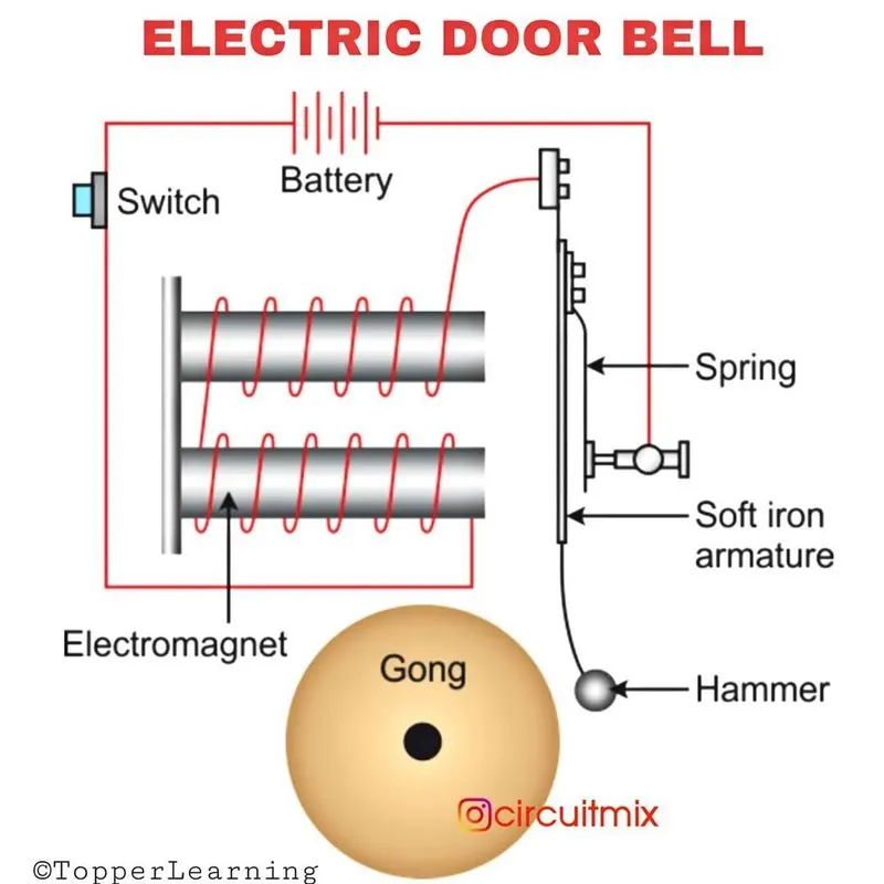
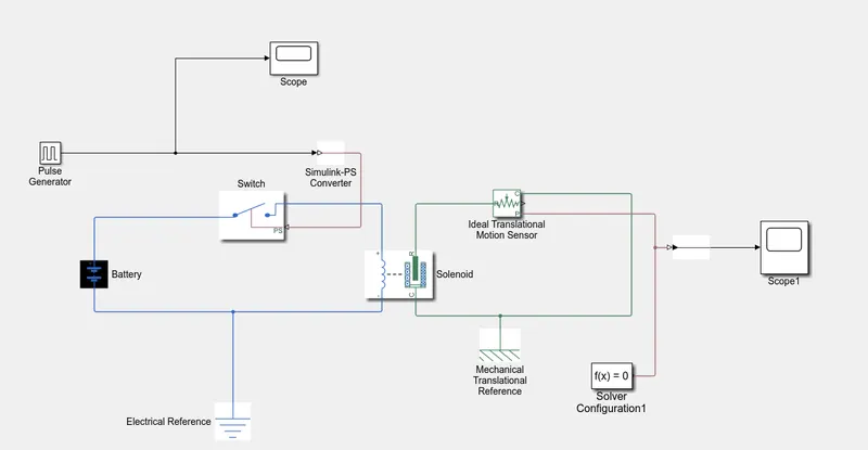
To create a simulink model of the same , we use the following blocks :
1. Pulse Generator
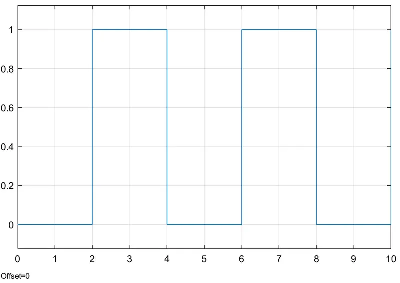
A pulse generator block is used to generate square wave pulses at fixed intervals. We can change the output of the waveform by adjusting the block parameters like Amplitude, Pulse Width , Phase Delay and Period. Here we are given a condition that the switch is ON for 2 seconds and then released. So a period of 4 seconds with a Pulse width of 50 % is assigned as the parameter values, so that we get a Turn ON pERIOD OF 2 Seconds. Amplitude is set to unity for convenience.
2. Battery
In our setup the positive terminl of battery is connected to the switch and the negative terminal is connected to the Electric Reference block.
3. Switch
The switch block represents a switch which is controlled by an external physical signal .
4. Solenoid Block
The solenoid block connected with the battery and switch completes an electric circuit. The Port C of the solenoid is connected with the Mechanical Translational reference block.
5. Electric Reference Block
This block acts as the ground in an electrical system. This is necessary if there is any electrical ports in your system.
6. Ideal Translational Motion Sensor Block
This block is used to observe the physical movement of the plunger. It has 4 ports :R,C,V & P.
7. PS - Simulink converter
This block converts a physical signals into the simulink output signals.
8. Simulink - PS Converter
This block converts simulink singals into the physical signals.
9. Mechanical Translational Reference Block
Any system with mechanical translation ports should have this block so that it acts as a reference point.
10. Solver configuration
For simulation , each physical system that is represented as a simscape block diagram requires this solver configuration block. The solver parameters are specified by this block which is required by the model before we begin simulation .
11. Scope
This block is connected to get the output. Here it is connected to the Ideal Translational Motion Sensor Block.
SIMULINK MODEL
INPUT PULSE
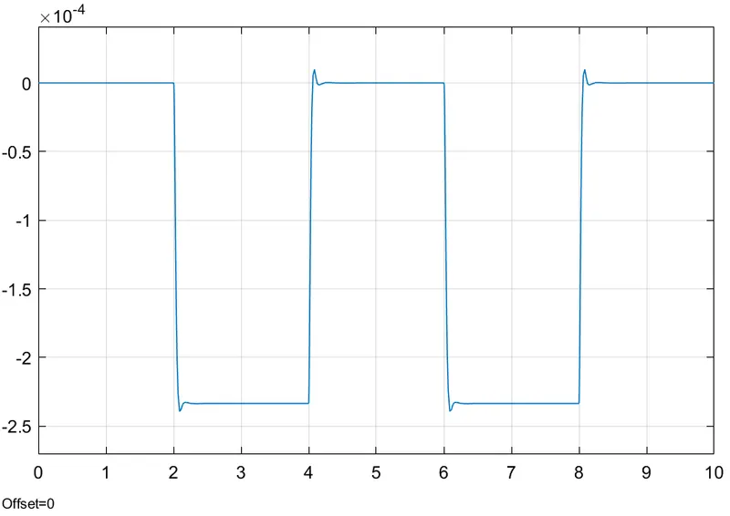
OUTPUT WAVEFORM
When Damping = 2N/(m/s)
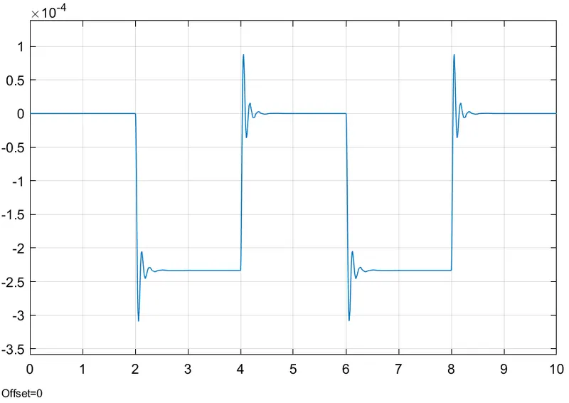
When Damping = 5 N/(m/s)
RESULT :
1. Simulation of the Doorbell using Solenoid is done .
2. The output of the simulation is analysed.
2. AIM : To use a thermistor in Simulink to sense the temperature of a heater and turn ON or OFF as per the following conditions :
Temperature source: 20 °C from 0 to 10 seconds, 27 °C from 10 to 30 seconds, 23 °C from 30 to 50 seconds
Fan conditions: ON if the temperature above 25 °C, OFF otherwise
THEORY
A thermistor is an electrical resistor whose resistance varies when there is change in the temperature, much more sensitive than the normal resistors in response to temperature variance.
MODEL :
To create the required model we need a Signal builder, Controlled temperature model, Thermistor, Thermal reference, Battery , Electric reference, switch, scope, voltage sensor , and other requisite models for smooth simulation like PS-Simulink converter and Solver configuration.Here the input signal is provided by the Signal builder block. The signal builder parameters are set according to the data provided here .
The Temperature :
20°C from 0 - 10 seconds
27°C from 10 - 30 seconds
23°C from 30 - 50 seconds
Fan conditions: ON if the temperature above 25 °C, OFF otherwise
The input signal created by the signal builder according to the given condition is as follows :
SCOPE RESULT
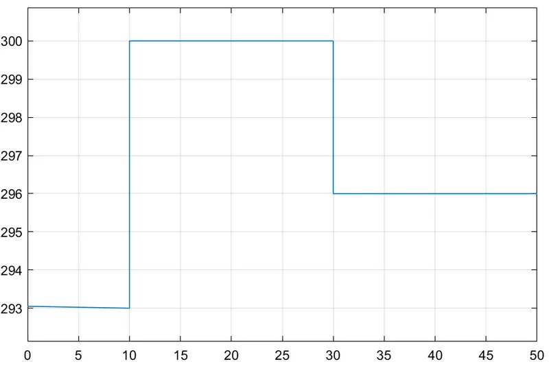
Here the Temperature is shown in Kelvin , so we convert the Celcius values into Kelvin scale and we get the corresponding values.
A battery is taken , whose positive port is connected to the Thermistor Block's positive port. The other side of the Thermistor block is connected to Resistor block which then completes the circuit by connecting to the negative port of the battery.
Simulation Model
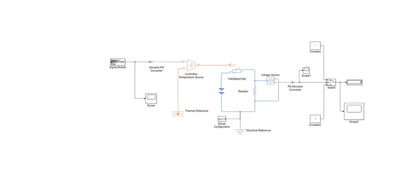
Inorder to measure the voltage across the Resistor block ,we employ a Voltage Sensor Block , which is connected in parallel to the Resistor block.
To provide the physical signal (i.e. Temperature here) we use the Controlled Temperature Source Block.
After creating the signal before connecting it to the system, we need to convert it into a physical signal using the Simulink - PS Converter Block .
The Port A of Controlled Temperature Source Block is connected to the Thermal reference block which acts as the reference point.While the Port B of the Controlled Temperature Source Block is connected to the Port A of the Thermistor block.
The voltage across the resistor is measured by the Voltage Sensor Block which is then connected to the PS-Simulink converter to convert the Physical signal into a simulink signal.
The output of the Voltage Sensor Block :
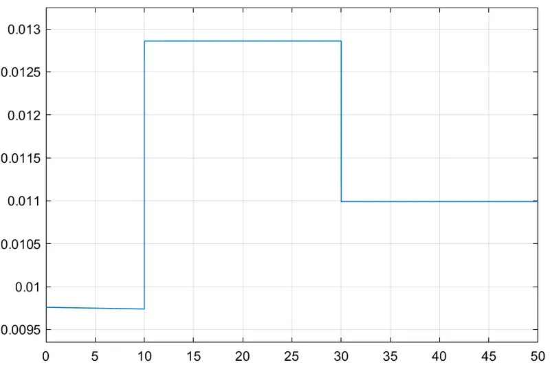
Here we can observe the voltage values as
For 20°C = 0.0098 V ,27°C =0.0128 V, 23°C = 0.011 V
So to apply condition that the Fan will be ON only if the temperature is greater than 26°C by adding a switch block which has a threshold in it that can be adjusted . We keep a threshold value here as .0111. The fan will be ON only if the temperature is greater than that.
A scope is also employed to see the output from the switch.
SCOPE FROM THE SWITCH :
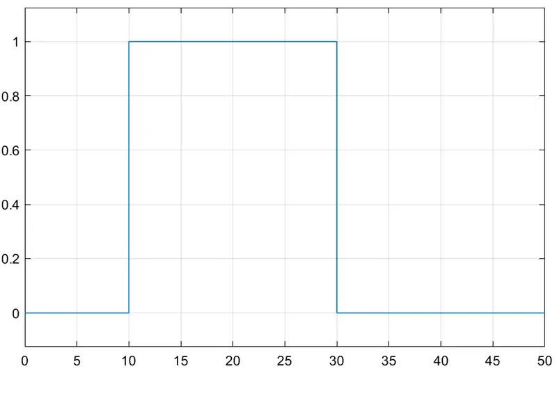
Here it is evident that FAN is only ON when the Temperature is 27°C ( i.e. greater than 26°C) , the same can be seen from the plot where the value is 1 from time 10 to 30 seconds. Rest of the time it is 0.
So the simulation is done and the results are thus obtained.