Week-7 Challenge: DC Motor Control
Aim:
1. To explain a MATLAB demo model named ‘Speed control of a DC motor using BJT H-bridge’, comment on the armature current shoot-up from the scope results and compare it with the H-bridge model.
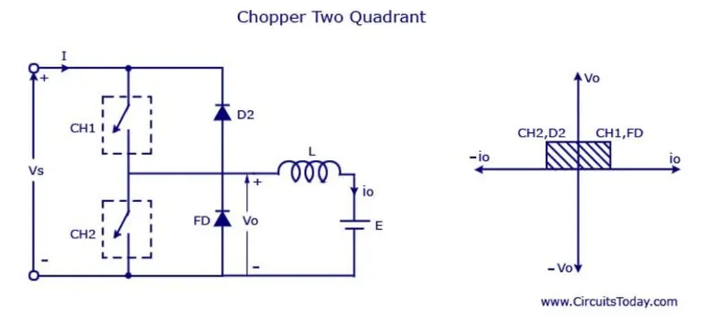
2. To develop a 2-quadrant chopper using Simulink & explain the working of the same with the relevant results.
3. To explain in a brief about the operation of the BLDC motor.
Solution 1:
Circuit Diagram of DC Motor using BJT H-bridge:
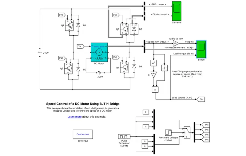
Inputs:
Total cycle time: 1 sec
Forward Motoring time: 0.5 sec
Reverse Motoring time: 0.5 sec
Battery Voltage: 240 V
Duty cycle: 75%
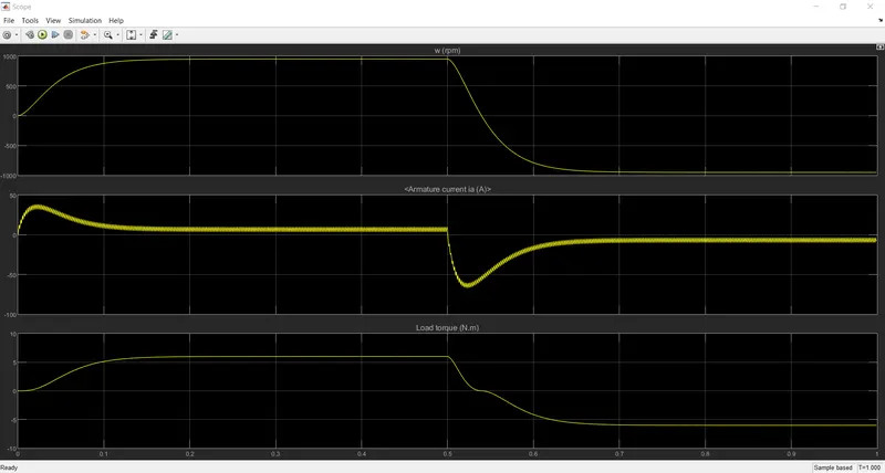
Simulating with 50% duty cycle:
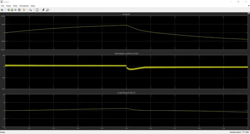
Simulating with 30% duty cycle:
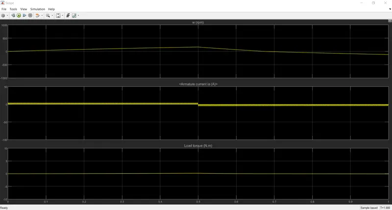
By changing the duty cycle to 30% the Armature current is doesn't shoot up when the motor changes direction from forward to reverse.
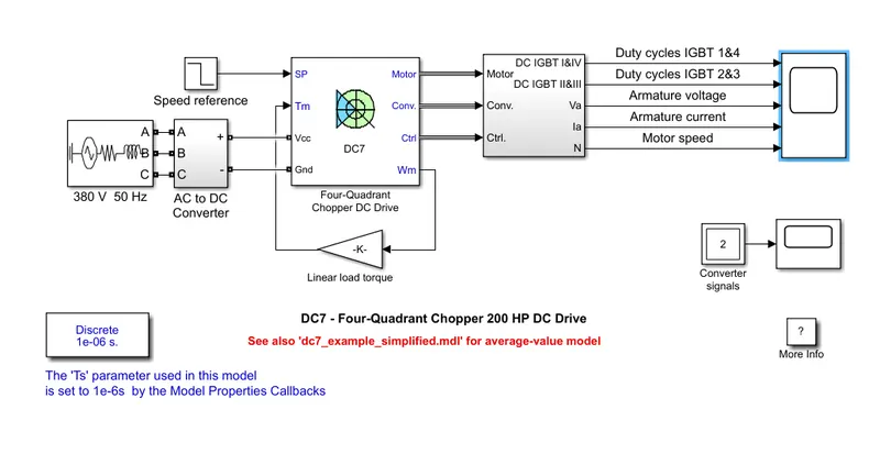
The 200 HP DC motor is separately excited with a constant 150 V DC field voltage source. The armature voltage is provided by an IGBT converter controlled by two Pl regulators. The converter is fed by a 515 V DC bus obtained by rectification of a 380 V AC 50 Hz voltage source. In order to limit the DC bus voltage during dynamic braking mode, a braking chopper has been added between the diode rectifier and the DC7 block.
The first regulator is a speed regulator, followed by a current regulator. The speed regulator outputs the armature current reference (in p.u.) used by the current controller in order to obtain the electromagnetic torque needed to reach the desired speed. The speed reference change rate follows acceleration and deceleration ramps in order to avoid sudden reference changes that could cause armature over-current and destabilize the system. The current regulator controls the armature current by computing the appropriate duty ratios of the 5 kHz pulses of the four IGBT devices (Pulse Width Modulation). For proper system behavior, the instantaneous pulse values of IGBT devices 1 and 4 are opposite to those of IGBT devices 2 and 3. This generates the average armature voltage needed to obtain the desired armature current. In order to limit the amplitude of the current oscillations, a smoothing inductance is placed in series with the armature circuit.
Output:
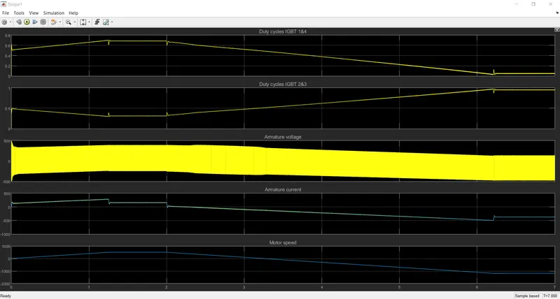
When T = 7 seconds
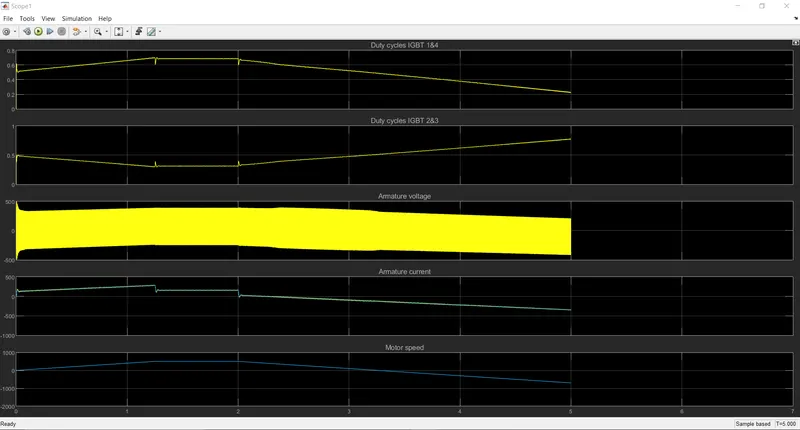
When T = 5 seconds
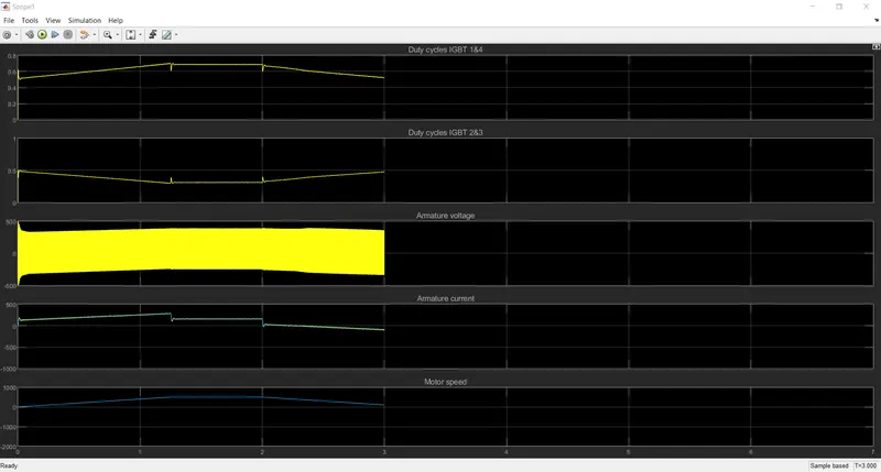
When T = 3 seconds
Comparison of 'Four-Quadrant Chopper DC Drive (DC7) block' with H-bridge model:
• In H-Bridge we need to reverse the polarity to change the direction but in Four-Quadrant Chopper DC Drive it uses reference speed to change the direction of motor rotation.
• Pl controller is used for speed and current control in Four-Quadrant Chopper DC Drive is absent.
• The current shoot-up and distribution are high in H-Bridge because of the switching losses.
• In the H-Bridge can perform only the Forward & Reverse motoring. Whereas the Four-Quadrant Chopper DC Drive operates in 4 modes, Forward & Reverse Motoring and Forward & Reverse Braking.
• Regenerative braking is possible in Four-Quadrant Chopper DC Drive, where H-Bridge cannot.
Solution 2:
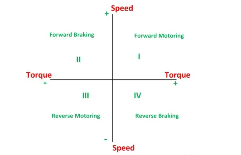
Circuit Diagram for 2-quadrant chopper:
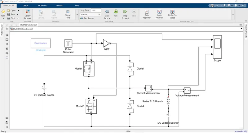
Circuit Diagram on Simulink:
Result:
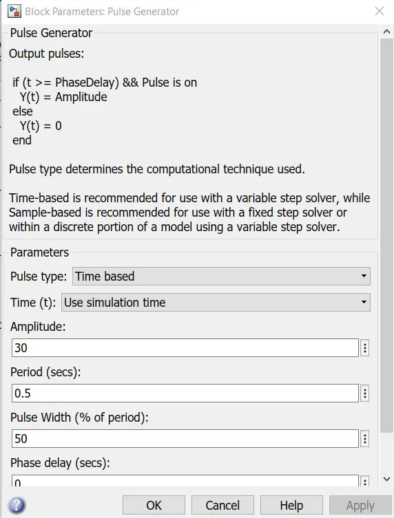
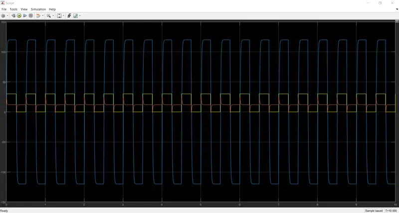
Output with the above parameters:
Solution 3:
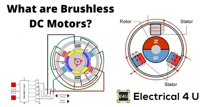
A brushless DC motor (also known as a BLDC motor or BL motor) is an electronically commuted DC motor that does not have brushes. The controller provides pulses of current to the motor windings which control the speed and torque of the synchronous motor.
These types of motors are highly efficient in producing a large amount of torque over a vast speed range. In brushless motors, permanent magnets rotate around a fixed armature and overcome the problem of connecting current to the armature. Commutation with electronics has a large scope of capabilities and flexibility. They are known for smooth operation and holding torque when stationary.
Working Principle and Operation of BLDC Motor
BLDC motor works on the principle similar to that of a conventional DC motor, i.e., the Lorentz force law which states that whenever a current-carrying conductor is placed in a magnetic field it experiences a force. As a consequence of the reaction force, the magnet will experience an equal and opposite force. In the case BLDC motor, the current-carrying conductor is stationary while the permanent magnet moves.
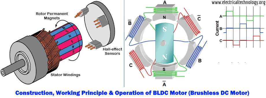
When the stator coils are electrically switched by a supply source, it becomes an electromagnet and starts producing the uniform field in the air gap. Though the source of supply is DC, switching makes to generates an AC voltage waveform with a trapezoidal shape. Due to the force of interaction between the electromagnet stator and permanent magnet rotor, the rotor continues to rotate.
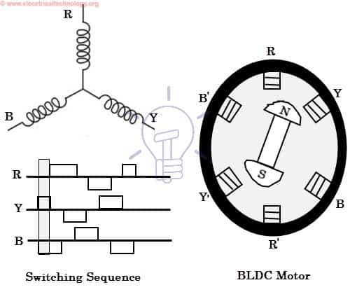
Consider the figure below in which the motor stator is excited based on different switching states. With the switching of windings as High and Low signals, corresponding winding energized as North and South poles. The permanent magnet rotor with North and South poles aligns with stator poles causing the motor to rotate.
Observe that the motor produces torque because of the development of attraction forces (when North-South or South-North alignment) and repulsion forces (when North-North or South-South alignment). In this way motor moves in a clockwise direction.
References: BLDC Motor.
Multi Quadrant Operation of DC Motor in Simulink
Speed Control of a DC Motor Using BJT H-Bridge Simulink Command
DC7 - Four-Quadrant Chopper 200 HP DC Drive Simulink Command