Week-7 Challenge: DC Motor Control
1.
A. Explain a MATLAB demo model named ‘Speed control of a DC motor using BJT H-bridge’.
Purpose:
In the model, the H-bridge circuit is used to enable the use the DC motor in either direction i.e., both forward and reverse direction.
Basic idea:
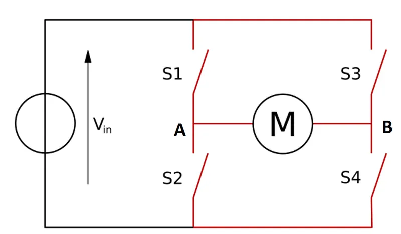
The basic H-bridge circuit is as shown below. This circuit is operated in two modes to allow motor rotation in the two directions,
Mode 1- Switches S1 and S4 are ON while S2 and S3 are off. The current flows from point A to B forcing forward motoring.
Mode 2- Switches S1 and S4 are ON while S2 and S3 are off. The current flows from point B to A forcing reverse motoring.
System description:
In the given model,
- The motor is driven by a 240 V battery.
- The circuit shown about is implemented by using BJT transistors for switches.
- Along with the switches, diodes are connected in parallel. These diodes help when there are sudden changes in voltages during switching i.e. by avoiding a consequent current change with an inductor in the circuit.
- In the model, this motor is used to drive a vehicle model where the torque required by the motor is directly proportional to the square of the angular velocity at the wheel of the vehicle.
Control operation:
To apply the control logic as explained above, the below 'signal generating circuit' is used,
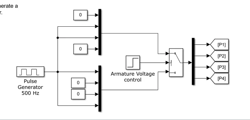
Here, a switch is used to toggle between the two modes mentioned above. The switching signal is designed for a simulation of 1s with and to switch from mode 1 to 2 at 0.5 s. A pulse generator is used to generate a PWM signal at 500 Hz with a 75% duty-cycle to control the motor speed. The duty cycle will be proportionate to the motor speed produced.
Result:
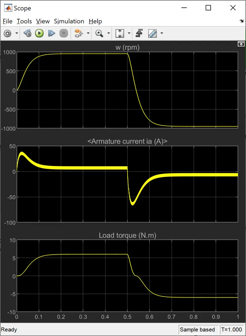
The result seen in the scope as shown below, shows that the expected result is achieved i.e.the angular velocity is positive until 0.5 seconds and starts to move towards negative direction from then on. It reaches a steady negative value and stays there for the rest of the simulation.
B. Comment on the armature current shoot-up from the scope results.
The shoot-ups in the armature current during the start and the switching stage is the transient behaviour of the system. These dynamics are caused in the system due to the present of motor inductance. These overshoots could be reduced by use of feedback control for sending the PWM signal rather than sending a constant 75% duty cycle signal as in the model.
C. Refer to the help section of ‘The Four-Quadrant Chopper DC Drive (DC7) block’. Compare it with the H-bridge model.
- A chopper circuit is used to output a variation on the input DC voltage. In 'The four-Quadrant Chopper DC Drive (DC7) block' model, a four-quadrant chopper is used to operate a DC motor.
- An H-bridge circuit, is generally used to change the switch polarity of voltage to load [Wikipedia]. The model discussed above, it is used to operate a DC motor.
- Although the basic switching circuit structure is the same for a 4 quadrant chopper and an H-bridge, they vary in the way they are implemented and operated, as listed below,
| Four-Quadrant chopper | H-bridge |
|
The motor is operated in all quadrants/mode i.e.,
|
The motor is operated only in two quadrants/modes i.e.,
|
| Generally used in industrial and commercial applications | Used in low-current rating technologies |
| Control circuit is more complex. Obviously, due to operation in 4 modes. As seen in the model, we 2 variables that are controlled i.e., motor velocity and armature current | Control circuit is simpler. As seen in the model, only armature voltage is controlled. |
| In the mentioned chopper model, IGBT type switches are used for implementation | In the H-bridge model, BJT type switches are used. |
2. Develop a 2-quadrant chopper using simulink & explain the working of the same with the relevant results. (Refer to article - Multiquadrant operation of motor )
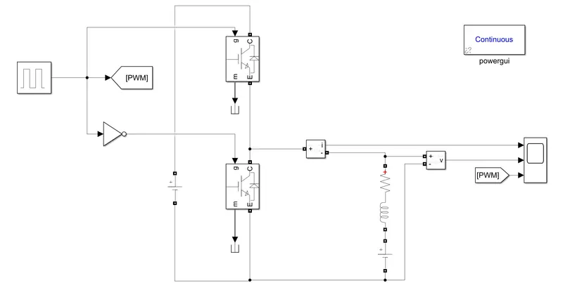
A 2-quadrant chopper (that operates in the first and the second quadrant) is developed in Simulink as shown below.
Circuit description - The chopper circuit usesIGBTs for switching as shown, with diodes connected to it such that, it allows current 'the other way'. At the input of the chopper, a 100V voltage source is used to emulate the battery of a vehicle. At the output of the chopper, there is an RL circuit and a voltage source is used to emulate the motor armature resistance and inductance as well as the back-emf generated. A pulse generator is use to control the switching of the chopper.
Working -
In first quadrant operation, the upper chopper (Ch1) is operated and the lower chopper(Say Ch2) is OFF. When Ch1 is ON, the current passes from battery ->Ch1 -> output(motor). When Ch1 is OFF, stored energy in the inductance dissipates through diode in lower diode (say D2). In either case, both armature current and voltage are positive!
In the second quadrant operation, Ch1 is OFF while Ch2 is operated. When Ch2 is ON, the current passes from motor (due to back emf)->Ch2. When Ch2 is OFF, current passes through upper diode (say D1). In either case, armature current is negative while voltage remains positive i.e. working in second quadrant.
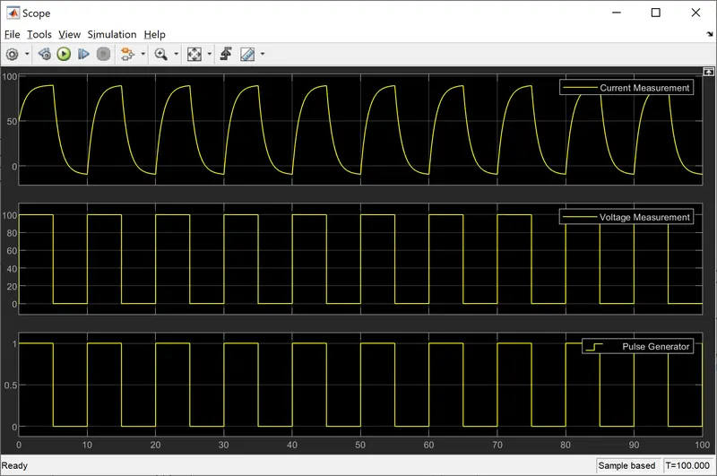
Results - The above explanation of a 2-quadrant chopper working, is illustrated below. The chopper is operated in the first quadrant upto around the first 73% of the period of the pulse signal after which, the armature current becomes negative.
3. Explain in a brief about operation of BLDC motor.
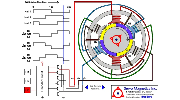
The BLDC motor has an inner rotor that consists permanent magnets and an outer stator that is excited by winding (at different phases) to generate magnetic field(s). The main difference between BLDC and Brushed DC motor is that, in Brushed DC motors, mechanical communation is used while in the BLDC, electrical commutation is used.
Working- The armature windings are excited by current creating a magnetic field which results in the motion of the permanent magnet rotor. Of course, for such a motion to be continued, there needs to be a variation in magnetic fields. This variation is brought about by supplying the DC current into the stator in alternating 3 phases such that the desired rotor motion is maintained. This commutation is illustrated in the picture below. Furthermore, a decoder circuit is used to transform the DC supply into 3 phases as required. This decoder circuit allows switching between the 3 phases of current as also shown in the animation below.