Week -2
1.
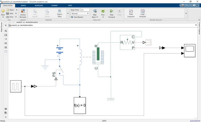
The required simulation of a doorbell is built as shown in the figure below.
System description:
A solenoid block is connected to a battery in series with a switch. This switch represents the "calling bell". When the switch is on, the circuit is closed resulting in an electromagnetic force in the solenoid which moves the plunger. To measure the displacement of the plunger, a motion translation sensor is used.
Input signal:
In reality, in general, in a doorbell, there will be a mechanism to close and open the circuit when the the switch at the door is pressed. For simplicity, in our simulation, we emulate this mechanism by sending a PWM signal as input to the switch block through a simulink to PS converter.
Output singal:
When the distance b/w plunger and solenoid is reduced, the hammer of the bell hits the gong and produces sound. Hence, the output of the translation sensor is the signal we are interested in.
Results:
The simulation result is shown below with the output signal shown at the top and the input "bell signal" shown at the bottom.
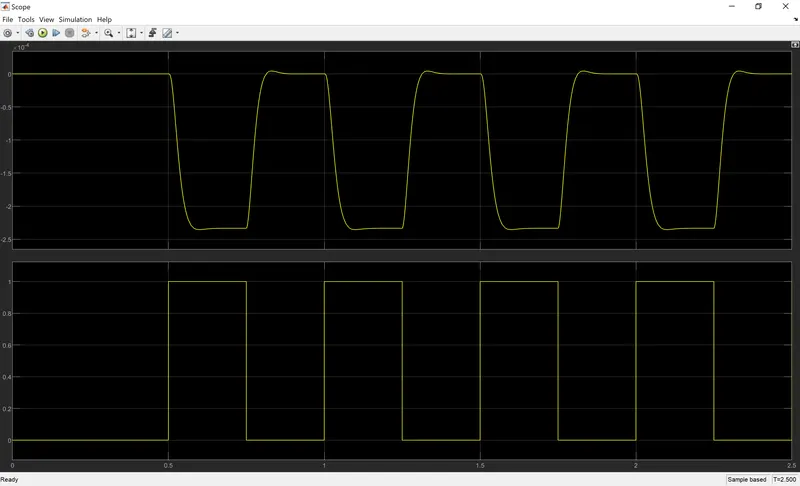
It is seen that when the bell is held for 2 seconds from 0.5s till 2.5a, the the hammer keeps hitting the gong repeatedly!
Note: In reality, the gong could be modelled by say, a mass-spring-damper system. However, in this simulation, for simplicity, we just assume that the hammer hits the gong when the output signal is reduced to a value of around -2.25e-4.
2.
Summary:
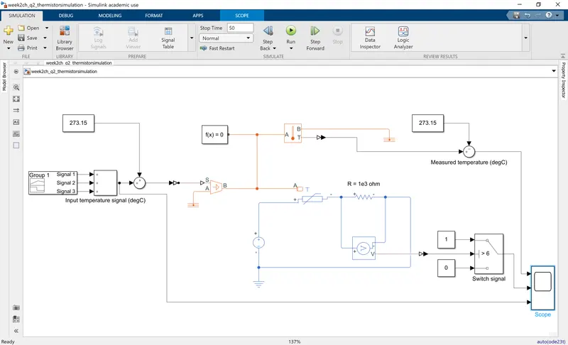
The required simulation of using a thermistor for temperature control of a heater is built as shown in the figure below. Following the figure, a description of the model and analysis of result is given.
System description:
- A controlled temperature source is used to represent the heater, the output of which is connected as the heat source to the thermistor block.
- The thermistor in series with a resistor is connected to a voltage source of 12V
- The variation is temperature alters the thermistor resistance due to which there is variation in the voltage across the thermistor and resistor. Hence, the voltage across the resistor can be used as a measure for heater temperature. This is done by using a voltage sensor block.
Calibration:
We are required to operate a switch based on whether the temperature is above or below 25 degC (298.15 K). Hence, we would want to know the voltage value of voltage sensor output at this temperature. For this, a simulation was run with input temperature at 25 degC and was seen that this corresponds to a voltage value of 6V (with the value of resistor being 1e3 Ohms and other blocks used with default settings). The simulation used for this calibration is attached with to this report.
Construction of required input signal:
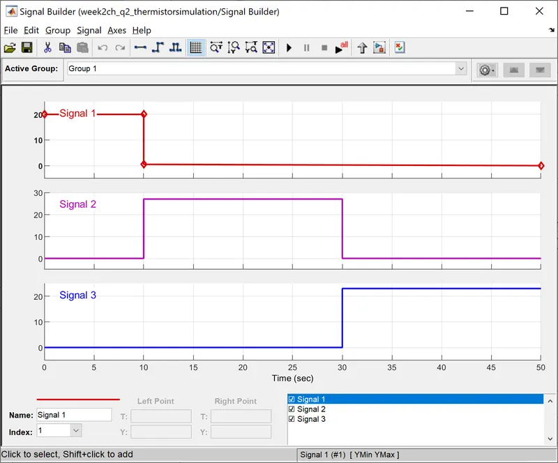
The given input signal is contructed using a signal builder block as shown below. Here, 3 "sub-signals" are used (for each temprature value) that are added together using a sum block. A value of 273.15 is added to the combined signal to convert to Kelvin. It is then sent to pysical system using simulink to PS converter.
Result:
The physical signal of the volatage sensor is converted to simulink signal using PS-simulink converted. This is used as switching signal for the "Fan switch"
A simulink switch block is used to simulated the "Switch to the fan", the threshold for which is set to 6V with output=1 implying "ON" and output =0 implying "OFF". The simulation is now run and the result is as shown below.
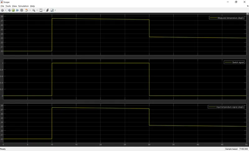
It is seen that the fan is turned On when the temperature is >25 degC and switched Off otherwise.