Week-6 Challenge: EV Drivetrain
1. Which types of power converter circuits are employed in electric and hybrid electric vehicle?
The following types of power-converters are used in electric and hybrid-electric vehicles:
- Rectifiers (AC to DC converters) - These are used for for example in charging stations where the AC supply need to be converted to DC current as required for charging EV battery.
- Inverters (DC to AC converters) - In case of some EVs, we have AC motors that require AC current to run the motor. In these cases, an inverter is used to convert DC current output from the battery to AC current as required, to supply the motor.
- Choppers (DC to DC converters) - EVs may require a different levels of voltage supplies for it's different components. For example, it's auxilliaries may require a lower level of voltage to power it. In these cases, choppers are used to step-down the DC voltage level.
AC to AC converters generally do not find a place for application in EVs
2. An Electric Vehicle's powertrain with 72V battery pack in shown in the diagram below. The duty ratio for acceleration operation is 'd1' and for the braking operation the duty ratio is 'd2'.
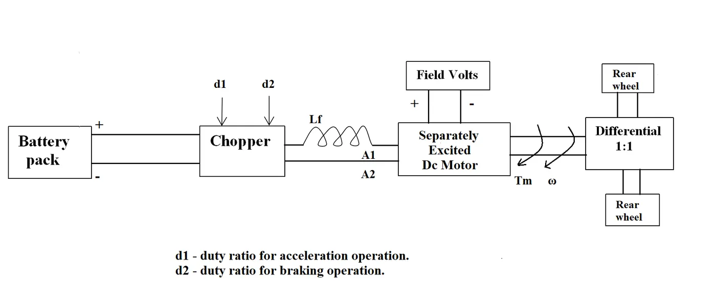
The other parameters of the electric vehicle is given below,
Motor and Controller Parameters:
Rated Armature voltage= 72 V
Rated armature current= 400 A
Ra= 0.5Ω, KΦ= 0.7 Volt second
Chopper Switching frequency= 400 Hz
The vehicle speed-torque characteristics are given by the below equation

What is EV steady state speed if duty cycle is 70%?
We have from the motor model equation that,
`\omega = \frac{V}{K\phi} + \frac{Ra}{K\phi^2} T`
Using the values given in the question, with `V = Va*d1`, we get the equation,
`\omega = 72 - 1.0204T`
and hence, the motor torque will be,
`T = \frac{72 - \omega}{1.0204}`.
Since we have a 1:1 gear ratio from the motor to the wheel, we must have the motor torque and angular velocity to be the same as that at the wheel. So we have,
`Tv = |T|`.
this gives two possible equations which we will now consider,
considering `Tv = T` gives equation,
`0.0052\omega^2 - \omega +46.7961 = 0`.
This quadratic equation is solved using roots() function in MATLAB and we get solutions for `\omega` as,
`\omega = 111.85 rads^{-1}, 80.45 rads^{-1}`.
However, both these values result in negative torque T as we can see from the derived motor torque equation. This is not the convention we consider. We consider that a positive torque results in a positive angular velocity. So these solutions are ignored.
Next we consider, `Tv = -T` which gives the equation,
`0.0052\omega^2 + \omega -46.7961 = 0`.
The solutions to this quadratic equation are,
`\omega = -231.23 rads^{-1}, 38.92 rads^{-1}`.
Ignoring the negative value, we have the solution for steady-state speed as `\omega = 38.92 rads^{-1}`and the corresponding vehicle torque as `T = 32.42 Nm`!
Result: `\omega = 371.66 rpm`.
3. Develop a mathematical model of a DC Motor for the below equation using Simulink.
ω">ωω= V/Kϕ">ϕϕ -Ra/Kϕ">ϕϕ^2 .T
The required motor model is developed in Simulink as shown below,
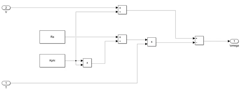
The associated simulink model 'w6ch_q3_simulink.slx' is attached.
The illustration can be seen by running the file 'w6ch_q3_simulink_run.slx'. Simulation result show the linear mapping between torque and angular velocity of the motor i.e. linear with negative slope.
4. Refer to the blog on below topic:
Induction Versus DC brushless motors by Wally Rippel, Tesla
Explain in brief about author’s perspective.
In this blog, the author compares the BLDC and the induction motors as prospects for use in the electric vehicle domain. First, he briefly describes the two motors highlighting their similarities and then, goes on to enumerate their pros and cons in the EV context. Finally, he states his opinion on the which type of motor could find place in the future.
Below, the main points of this blog are summarized,
- Both type of motors are similar in their stator structure i.e. current carrying windings are used to induce a magnetic field. However, they differ in the structure of the rotor i.e., permanent magnets are used in BLDC while steel laminations are used in Induction motors.
- The Induction motor has the main advantage that, they can be operated directly with conventional utility power while BLDC motor would require an inverter for this purpose. On the other hand, the induction motor is limited by it's starting torque and running peak torque capabilities. The author argues that, these limitations of the induction motor could be overcome by incorporating 'smart feedback control inverter' and would then provide competetion for DC motors in EV applications. Although, still providing lower torque performance.
- Further advantage of BLDC is - lower heat is produced in rotor and hence could perform at higher energy efficiency than induction motor.
- Howerver, disadvantages of BLDC are - Magnetic field B can't be easily varied for varying loads resulting in higher losses and this also means, losses increase with increase in size of motor. So induction motors are favoured when higher performance is required. Lastly, the PMs in BLDC make them more expensive and harder to handle since a magnetic field is always active.
- In conclusion, he states that, at the present (as of 2007) BLDC motors will be favored in EV applications. However, he wonders whether the induction motor could become relevant when higher performance is required from an EV vehicle in the future.