Week-7 Challenge: DC Motor Control
Week 7 Challenges : DC Motor Control
Q1. A. Explain a MATLAB demo model named ‘Speed control of a DC motor using BJT H-bridge’.
B. Comment on the armature current shoot-up from the scope results.
C. Refer to the help section of ‘The Four-Quadrant Chopper DC Drive (DC7) block’. Compare it with the H-bridge model.
Soln:
(A.)
The H-Bridge circuit is simple circuit used for controlling DC motors forward and backward movement. The circuit contains 4 switching elements with the load in the center forming a H- shaped structure. The switching elements can BJT, MOSFET or IGBT. The circuit switches the polarity of a voltage applied to a load allowing DC motor to run forwards or backwards.
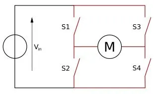
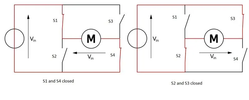
When the switches S1 and S4 are closed (and S2 and S3 are open) a positive voltage is applied across the motor. By opening S1 and S4 switches and closing S2 and S3 switches, this voltage is reversed, allowing reverse operation of the motor.
The switches S1 and S2 should never be closed at the same time, as this would cause a short circuit on the input voltage source. The same applies to the switches S3 and S4. This condition is known as shoot-through.
Matlab model :
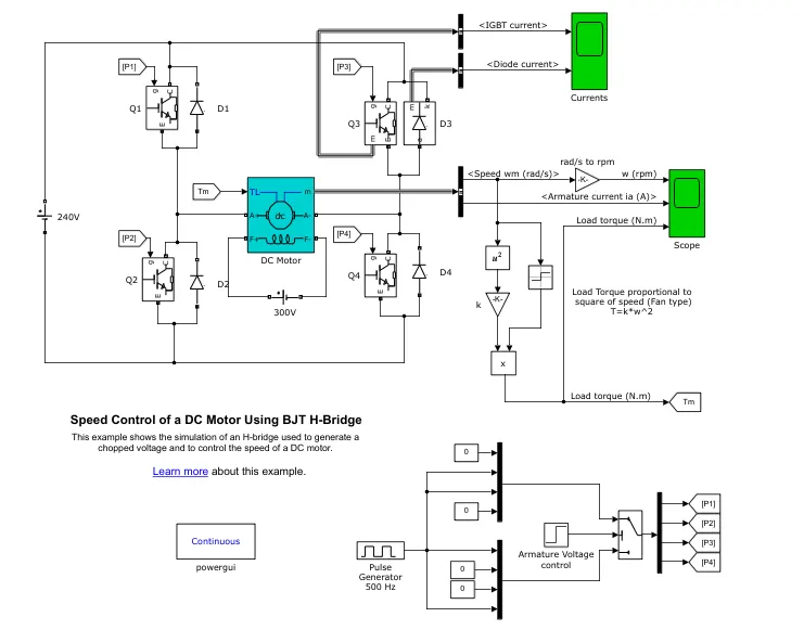
The block diagram of the MATLAB model for Speed Control of a DC motor using BJT H -Bridge is given below-
Model description:
The Bipolar Junction Transistor (BJT) when used for power switching applications, operates as an IGBT. When it is conducting (BJT operating in the saturated region), a forward voltage Vf is developed between collector and emitter (in the range of 1 V). Therefore, the IGBT block can be used to model the BJT device.
The IGBT block does not simulate the gate current controlling the BJT or IGBT. The switch is controlled by a Simulink® signal (1/0). The DC motor uses the preset model 5 HP 24V 1750 rpm. It simulates a fan type load where Load torque is proportional to square of speed. The armature mean voltage can be varied from 0 to 240 V when the duty cycle (specified in the Pulse Generator block) is varied from 0 to 100%.
The H-bridge consists of four BJT/Diode pairs (BJT simulated by IGBT models). Two transistors are switched simultaneously: Q1 and Q4 or Q2 and Q3. When Q1 and Q4 are fired, a positive voltage is applied to the motor and diodes D2-D3 operate as free-wheeling diodes when Q1 and Q4 are switched off. When Q2 and Q3 are fired, a negative voltage is applied to the motor and diodes D1-D4 operate as free-wheeling diodes when Q2 and Q3 are switched off.
Simulation results:
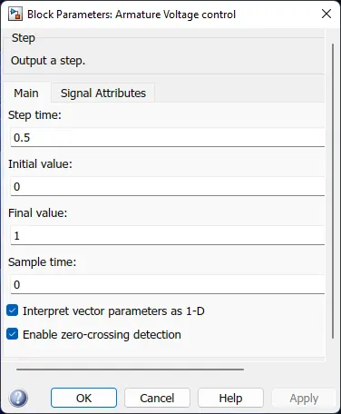
The motor is set to start in the positive direction with a duty cycle of 75% (i.e DC voltage of 180V). At t= 0.5 sec., the armature voltage is suddenly reversed and the motor runs in the negative direction.
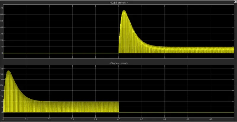
- From the current curve, we observe current flowing through diode D3 in the first 0.5 sec. In the later 0.5 sec, current flow is observed in Q3 IGBT.
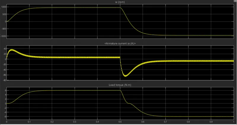
- The motor speed ramps up from 0 to top speed of 950 rpm in 0.25 sec. and stays there till 0.5 sec. After changing the polarity, speed drops to zero and then reaches to value of – 950 rpm, meaning that motor is rotating in the opposite direction.
- When the supply is turned on, the armature current jumps around to high value 38 Amps, then comes to a steady range of 4 to 10 amps. After the polarity is changed, the direction of the current changes and we observe negative current maxing at -66 Amps, indicating the opposite motion of the rotor.
- The Torque also increases steadily to reach the maximum value of 6 N-m at 0.22 sec. After the reversal of voltage, it reaches 0 at 0.54 second and then rises in the negative direction to a max value of -6 N-m.
(B.)
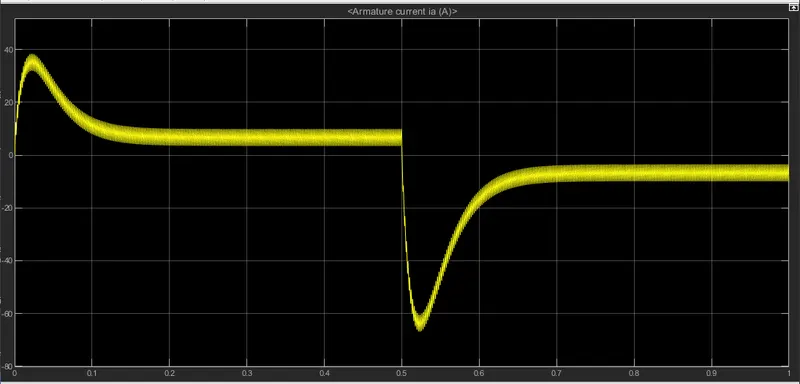
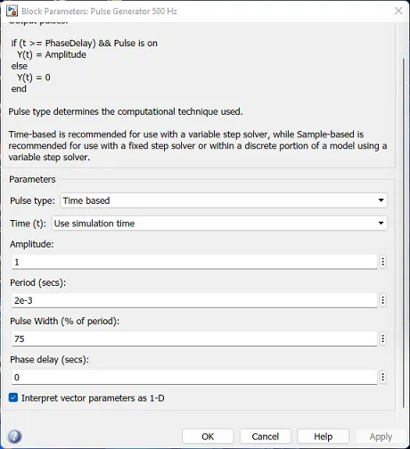
After running the simulation, we can observe the armature current spikes at 0.03 sec. during staring and at 0.53 seconds during the polarity change. The current is huge during spikes. It is due to the transient switching in the circuits. However this spikes can be overwhelmed by simply lowering the duty cycle of the signal. This can be done by changing the pulse width values in pulse generator block as follows-
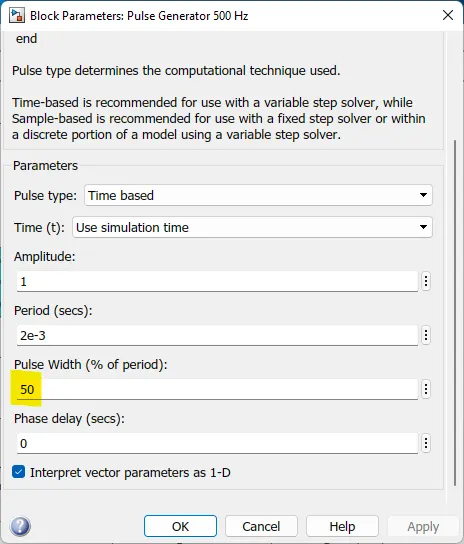
Now, with new new pulse width, the voltage supplied would be 120 Volts. The model is simulated and the results are fetched from scope.
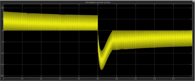
So, in this case the spikes are pretty much removed , however we also have to trade of some speed. Clearly, this method works but it requires to find balance between performance required and amount if spikes one can deal with.
(C).
The Four-Quadrant Chopper DC Drive (DC7): This example model shows the DC7 four-quadrant chopper DC drive during speed regulation of dc motor.
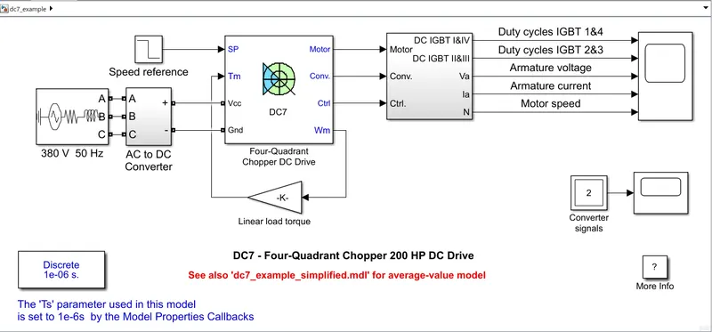
The 200 HP DC motor is separately excited with a constant 150 V DC field voltage source. The armature voltage is provided by an IGBT converter controlled by two PI regulators. The converter is fed by a 515 V DC bus obtained by rectification of a 380 V AC 50 Hz voltage source. In order to limit the DC bus voltage during dynamic braking mode, a braking chopper has been added between the diode rectifier and the DC7 block.
The first regulator is a speed regulator, followed by a current regulator. The speed regulator outputs the armature current reference (in p.u.) used by the current controller in order to obtain the electromagnetic torque needed to reach the desired speed. The speed reference change rate follows acceleration and deceleration ramps in order to avoid sudden reference changes that could cause armature over-current and destabilize the system. The current regulator controls the armature current by computing the appropriate duty ratios of the 5 kHz pulses of the four IGBT devices (Pulse Width Modulation). For proper system behaviour, the instantaneous pulse values of IGBT devices 1 and 4 are opposite to those of IGBT devices 2 and 3. This generates the average armature voltage needed to obtain the desired armature current. In order to limit the amplitude of the current oscillations, a smoothing inductance is placed in series with the armature circuit.
Simulation Results:
Before starting the simulation, set the initial bus voltage to 515 V via the GUI block ('Initial States Setting' button and 'Cbus' variable). The motor is coupled to a linear load, which means that the mechanical torque of the load is proportional to the speed. The model is simulated and results from scope is fetched.
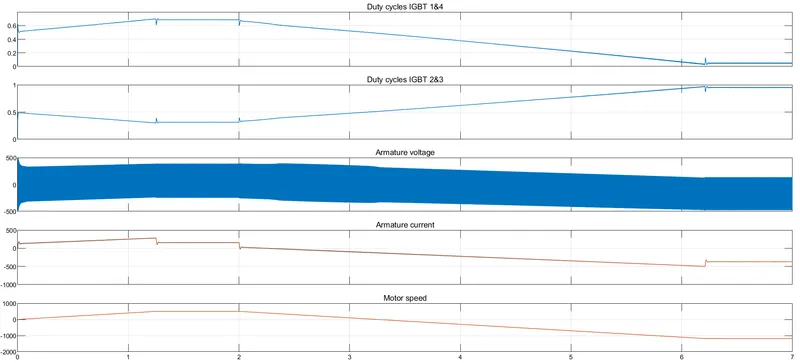
- The speed reference is set at 500 rpm at t = 0 s. Observe that the motor speed follows the reference ramp accurately (+400 rpm/s) and reaches steady state around t = 1.3 s.
- The armature current follows the current reference very well, with fast response time and small ripples. The current ripple frequency is 5 kHz.
- At t = 2 s, speed reference drops to -1184 rpm. The current reference decreases to reduce the electromagnetic torque and causes the motor to decelerate with the help of the load torque.
- At t = 2.2 s, the current reverses in order to produce a braking electromagnetic torque (dynamic braking mode). This causes the DC bus voltage to increase.
- At t = 3.25 s, the motor reaches 0 rpm and the load torque reverses and becomes negative. The negative current now produces an accelerating electromagnetic torque to allow the motor to follow the negative speed ramp (-400 rpm/s). At t = 6.3 s, the speed reaches -1184 rpm and stabilizes around its reference.
DC 7 model vs BJT H-model:
- The stability of voltage and current is high in four quadrant model compared to BJT H-model.
- High power levels and better efficiency is observed in DC 7 model.
- DC7 model has relatively high switching frequency than BJT H-model
- Regenerative braking in possible in four quadrant, which is cannot be achieved in the BJT model.
- In the dc 7 model, the armature current is chopped, but in BJT model current is continuous.
- The Dc7 model can work in four quadrants, whereas the BJT works only in two.
- To alter the direction of the motor current signals are interrupted in DC 7 model, but the BJT H-model voltage polarity is altered.
- The four-quadrant model is widely used in automotive sector for speed control of DC Motor, whereas BJT H-model found its application robotics (both general and industrial purposes) and other electro-mechanical devices.
Q2. Develop a 2-quadrant chopper using simulink & explain the working of the same with the relevant results. (Refer to article - Multiquadrant operation of motor )
Soln:
Two quadrant Chopper : The two-quadrant chopper, as the name suggests works only in two quadrants. This is mainly used for forward motoring and regenerative braking. The circuit diagram of this kind of chopper is given below-
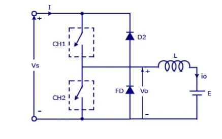
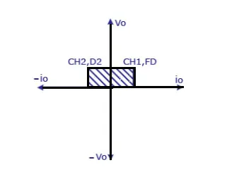
The average voltage is always positive in this arrangement. When the switch CH1 is closed and CH2 is opened, voltage is observed across the load. During this time current flows from source to load through the inductor, that results energy storage in the inductor. When the switch CH1 is opened, the freewheeling diode starts conducting and current flows from load to source. The load current becomes negative as CH2 is turned on, and current completes its path via D2 . One thing to avoid that the two switches should never be turned on at the same time, as this would short circuit the voltage source and potentially damage it.
Now , with the help of the above circuit a Simulink model is created.
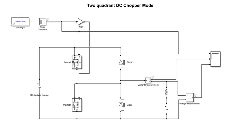
Two MOSFET blocks are used to act as switches. The DC Voltage source block is set provide 48 V in the source side and the other at the load side is set at 24 V. The pulses to switch is given by the pulse generator. The Not gate is used to prevent the triggering of both switches at the same time. To measure current and voltage , sensors are connected in the load side and scope is added.
Simulation results:
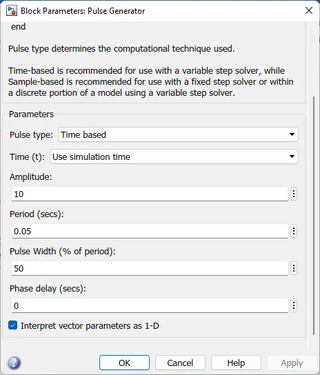
The current pulse of 10 A with period time of 0.05 sec. and 50% duty cycle is configured in the pulse generator block. The simulation is run for 1 sec. and results are taken from the scope.
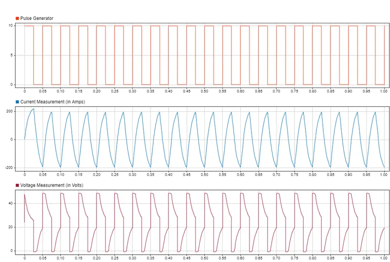
- From the curves it is observed, that voltage across load is always positive. Similar cannot be said for current.
- The current rises to peak value of 220 A and decreases to a negative value of around -190 A. The negative current is observed because of the switching of CH1 and CH2.
- The voltage sees a peak of 48 Volts and it decreases to 0. Then , When CH2 is closed , voltage increases again.
Q3. Explain in a brief about operation of BLDC motor.
Soln:
Brushless DC motor is kind of DC motor that does not implement brushes for energy supply. A brushless DC motors (BLDC) feature high efficiency and excellent controllability, and are widely used in many applications. Some common of uses BLDC motor are -
- Computer hardware and DVD/CD players
- Electric vehicles, hybrid vehicles, electric bicycles.
- Robotics and drones.
- Industrial robots, CNC machine tools, and simple belt driven systems
- Washing machines, compressors and dryers
- Fans, pumps and blowers.
Construction :
BLDC motor consist of stator and rotor without brushes. The rotor consist of Permanent Magnets and The stator consists coils and windings. There are 3 coils in the stators and 6 electrical wires extending from it. In most implementations 3 of these wires are connected internally, with the three remaining wires extending from the motor body.
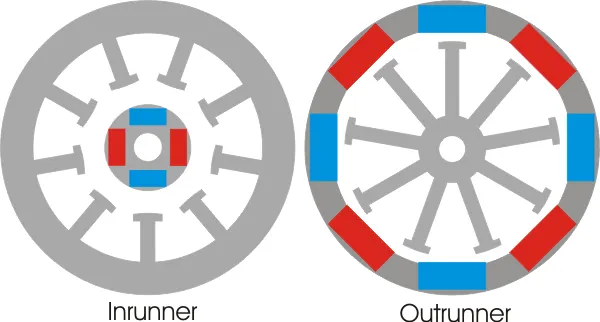
Depending on the position of the rotor BLDC motor can be divided into 2 types-
- Inrunner or Inner motor : The rotor stays inside the stator windings. In this construction heat dissipation is easy. They are used in high torque applications.
- Outrunner or outer motor: The rotor stays at the periphery surrounds stator that stays at the core. These magnets at the rotor traps the heat inside , so they are used in low current applications.
Operation of BLDC motor:
Bldc motor works based on the attraction and repulsion between the magnetic poles of rotor and stator. The coils in the stator are energized with dc supply that forms electromagnetic poles and attract the opposite of the poles of the permanent magnet rotor. The rotor magnet tries to align with the energized electromagnet of the stator, and as soon as it aligns, the next electromagnet is energized. Thus the rotor keeps running. An Electronic Controller (with hall effect sensor) is used to control the stator winding supplies with respect to the rotor movement.
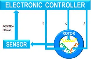
Considering A,B,C be the stator windings of 2 pole BLDC motor as shown in the animation, at first the coil A in energized. The rotor is attracted to the opposite pole . As soon as the rotor magnet reaches A, the coil B is energized with opposite polarity so that motor keeps moving in the same direction. As the rotor nears B, coil C is energized . When the it reaches C, the coil A is again energized , but in opposite polarity from before. And a result rotor keeps on moving due to attraction of opposite poles. This process is repeated to get constant movement of the rotor.
Here only one coil is powered at one instant. To improve the performance of the motor we can power 2 coils in such a way that the coil ahead of the rotor attracts and the coil behind repulses the rotor. This combined effect gives more torque and power output to suit the demand.
The energizing of the coils is taken care of by a electronic controller. A sensor is used to determine the position of the PM rotor, based on the position the controller energizes the coils accordingly. A hall effect sensor sees wide use for this purpose.
The operation of BLDC motor is quite similar with the old tale of carrot and donkey. Like donkey tried to get the carrot, the rotor also tries to align with stator but it never does so and keeps on rotating.
The Brushless DC Motor has significant advantages over the Brushed DC Motor and AC Induction motor. The advantages of using BLDC motor are-
- Less overall maintenance due to absence of brushes
- Reduced size with far superior thermal characteristics
- Higher speed range and lower electric noise generation.
- It has no mechanical commutator and associated problems
- High efficiency and high output power to size ratio due to the use of permanent magnet rotor
- High speed of operation even in loaded and unloaded conditions due to the absence of brushes that limits the speed
- Smaller motor geometry and lighter in weight than both brushed type DC and induction AC motors.
- Long life as no inspection and maintenance is required for commutator system
- Less electromagnetic interference
Referrences:
- https://www.electrical4u.com/brushless-dc-motors/
- https://in.mathworks.com/help/physmod/sps/ref/twoquadrantchopper.html
- https://www.lesics.com/brushless-dc-motor.html