Week -2
Answer to the Q no-1:
Objective : To make a Simulink model of doorbell system using solenoid block and observe the physical movement of the plunger.
Model :
The given reference diagram is as follows-
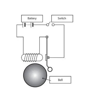
So to design the model in Simulink , we will be requiring the following blocks-
- Battery
- Switch
- Solenoid
- Ideal translational motion sensor
- Pulse generator for input signal
- Solver configuration
- Mechanical Translational Reference
- Electrical Reference
- Scope
Steps to model :
- The positive end of the Battery block is connected to the Switch and the negative end is connected to negative of Solenoid block.
- Then the switch is connected to the positive end of the Solenoid.
- For the input signal a Pulse Generator is used with desired parameters and the signal is fed to the Switch block via Simulink-PS Converter block since Switch is a physical block .
- A scope is connected to pulse generator block to observe the input.
- In the Solenoid block, the port R is connected to the input port R of the Ideal Translational Motion Sensor Block.
- Both the C port of solenoid and ideal translational motion sensor block is connected to a common Mechanical Translational Reference block.
- The output of the Ideal Translational Motion Sensor block is taken from the port P , which gives the displacement signal of the plunger . The port P is connected to a Scope via PS-Simulink Converter block.
- A Solver configuration block is added to port P of the sensor.
- An electrical reference is added to electrical network near the battery.
Hence our model is finished.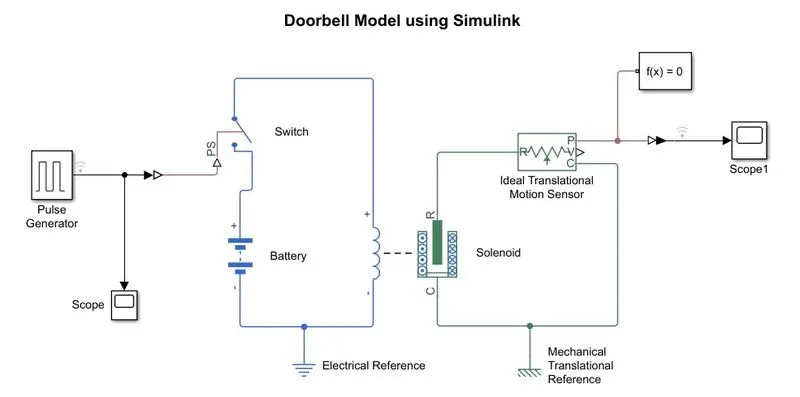
Results:
In this model, when the switch is closed the solenoid receives electrical power from the battery and pulls the metal arm to hit the bell producing sound.
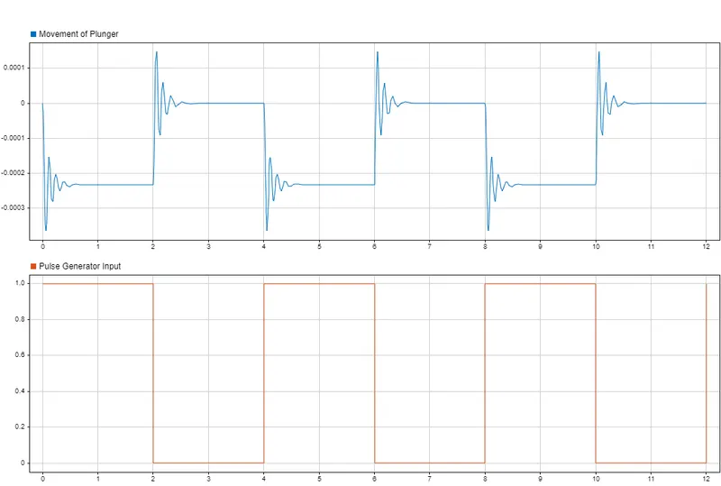
To create a situation where the switch is closed for 2 seconds and then released, the pulse generator is configured to have amplitude of 1 for time period of 4 sec with pulse width of 50% that will give us 2 sec of on time and 2 sec of time. The switch is configured to have a threshold of 0.9 meaning when input is greater than 0.9 , switch will be closed.
Now, the model is simulated for 12 seconds and the result plot is fetched from scope. From the plot it is observed that in the first 2 seconds,when the switch is closed there is Movement in the plunger which causes the bell to ring . In the next 2 second of the cycle,when the switch is open, we also see movement as the plunger moves to its original position.
Answer to the Q no. 2:
Objective- To use a thermistor to sense the temperature of a heater & turn on or turn off the fan as per below conditions:
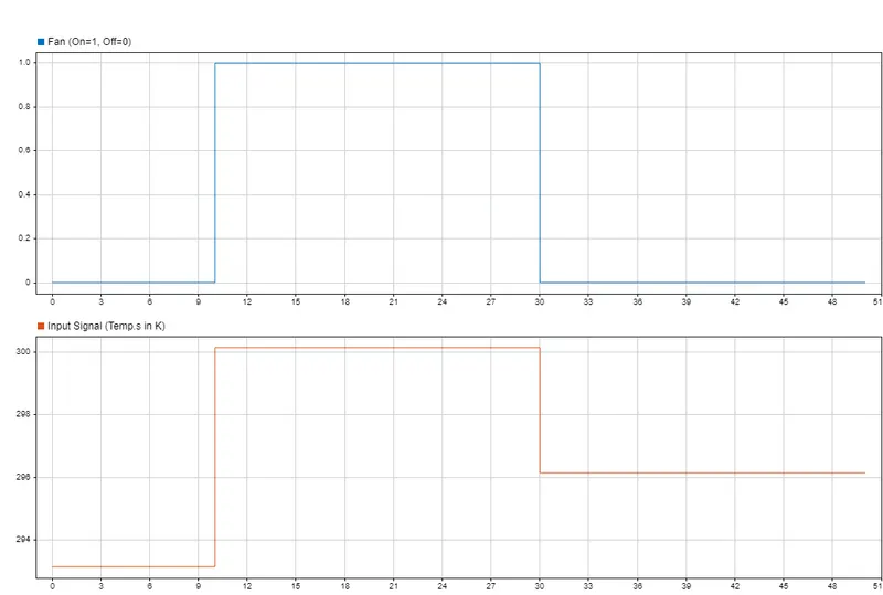
Temperature source: 20 °C from 0 to 10 seconds, 27 °C from 10 to 30 seconds, 23 °C from 30 to 50 seconds
Fan conditions: ON if the temperature above 25 °C, OFF otherwise.
Model- A typical model is build in Simulink to carry out the test.
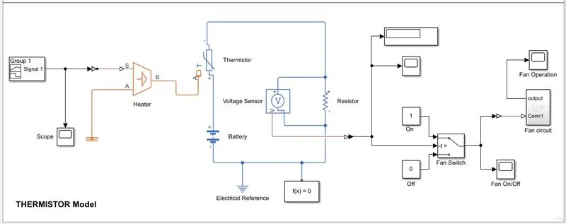
- To represent a heater , a Controlled Temperature Source block is used. Port A of the heater block is connected to a thermal reference and port B is connected to the A port of thermistor block.
- The input temperatures are converted into K and the input signal is build in the signal builder. So revised conditions becomes as follows-
0 to 10 seconds => 293.15 K ; 10 to 30 seconds =>300.15 K ; 30 to 50 seconds => 296.15 K
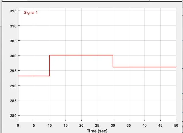
- The input signal is then fed to port S of Temperature source(Heater) via simulink-ps converter.
- The port B of heater block is connected to port A of Thermistor block.
- The thermistor block is configured to give high output if the temperature exceeds 25 degree C or 298.15 K.
- The thermistor is connected to an electrical circuit comprising a battery, resistor and voltage sensor.
- The +ve port of thermistor is connected to +ve of the battery and the -ve port is connected to resistor. Then the battery and the resistor are connected.
- The voltage sensor is connected across the resistor . The output the sensor is connected a Switch Block.
- If the input is high enough then the thermistor will trigger the switch block to give high output (1 or 'On') which will cause a fan to operate.
- The switch block is configured to have a threshold value of 0.01196 ,by applying the threshold value to the thermistor. So if the voltage sensor feds greater value then 0.01196 to the switch block , it will close the circuit and fan will turn ON; otherwise off.
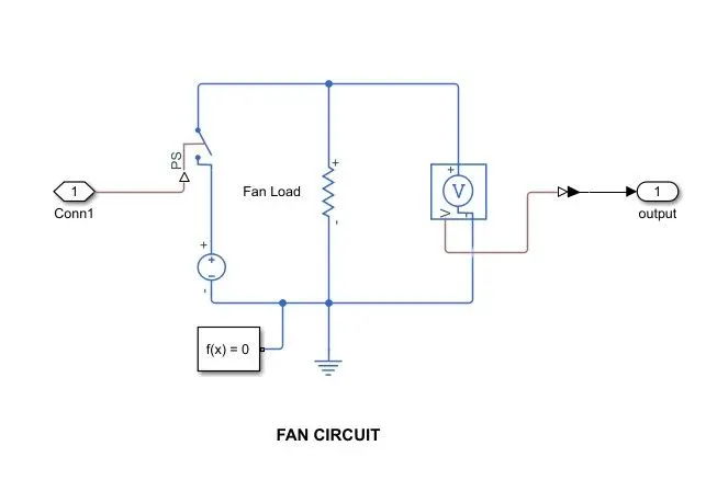
- Here a simple electrical circuit is considered for fan operation. A battery is connected to a resistive load representing the fan, through a switch.
- A voltage sensor is connected across the load to observe the output.
- Solver configurations and Reference (both Thermal and Electrical) were added where necessary.
Hence , the model is ready for simulation.
Results-
The model is simulated for 50 seconds and results are fetched from the scope. In the first 10 seconds temp. is 293.15 K, which is below the triggering temp. ,so we see the fan in off state. In the next 20 seconds, temp. is 300.15 K which triggers thermistor and causes the fan to operate. In the later 20 seconds, the temp. drops to 296.15 K , which is below 298.15 K , hence thermistor doesn't trigger and fan stays off.