Week-7 Challenge: DC Motor Control
DC MOTOR CONTROL
AIM:
- A. Explain a MATLAB demo model named ‘Speed control of a DC motor using BJT H-bridge’. B.Comment on the armature current shoot-up from the scope results. C.Refer to the help section of ‘The Four-Quadrant Chopper DC Drive (DC7) block’. Compare it with the H-bridge model.
- Develop a 2-quadrant chopper using simulink & explain the working of the same with the relevant results. (Refer to article - Multiquadrant operation of motor)
- Explain in a brief about operation of BLDC motor.
1.Explain a MATLAB demo model named ‘Speed control of a DC motor using BJT H-bridge’.
Introduction and Theory:
DC Motors as the other Motors works based on the principle that A Current carrying conductor placed in Magnetic Field experience Force. In DC Motor, DC Power is supplied to the Motor for creating field and rotating. Field can be produced either by supplying DC Power or by using Permanent Magnets. DC Motors requires a DC Drive for its Operation. With the DC Drive, the Speed and Direction of the Motor can be controlled.
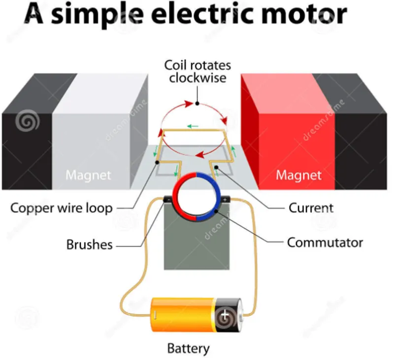
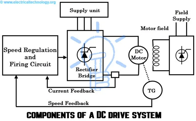
DC Drives are Power Electronic circuits that handle High Power and control the DC Voltage and Current supplied to the Motor. Power Electronic Circuits are made up of Semiconductive Devices that can handle High Power such as BJT, IGBT etc.
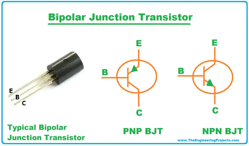
Bi-Polar Junction Transistor (BJT) is Current controlled Semiconductive Device with High Switching Speed and Power Handling Capacity. Small Current applied at Base controls the Large Current flowing between Collector and Emittor.
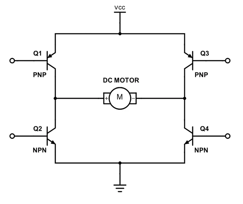
H-Bridge is a Simple Power Electronic circuit which uses 4 Transistors to control the Power supplied to the DC Motor which is connected to the center of the Bridge.
Simulink Model:
Model Description:
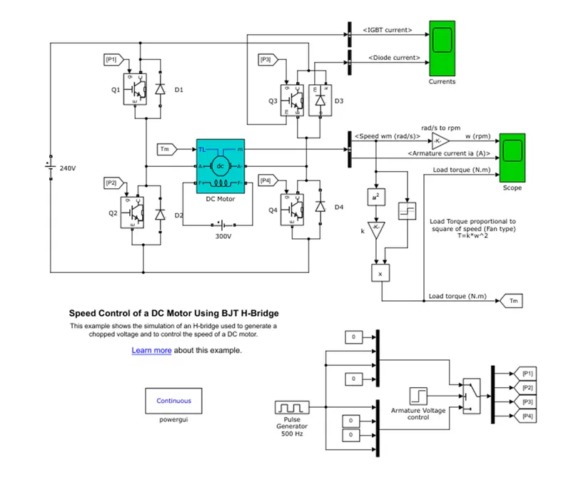
The Model uses 4 IGBT Blocks, 4 Diode Blocks to form a H-Bridge. The DC Motor Block is connected to the Center of the H-Bridge. Actually, The IGBT, Diode and DC Motor are Simscape Blocks which are Masked representation of a Sub-system.
A Separate Circuit is also created to give Gate pulses to the IGBT. As a Step Input is used to control the which IGBT need to be opened, For 0.5 seconds, When the step input is Zero, Gate pulse is supplied to Q1 and Q4 only and after that The Step Input becomes One Gate pulse is supplied to Q2 and Q3.
Duty Cycle is set as 75% through Pulse Generator.
The Output of the DC Motor is converted into its equivalent Load Torque (Aero Drag) and given as input to the DC Motor in a Closed Loop.
Output:
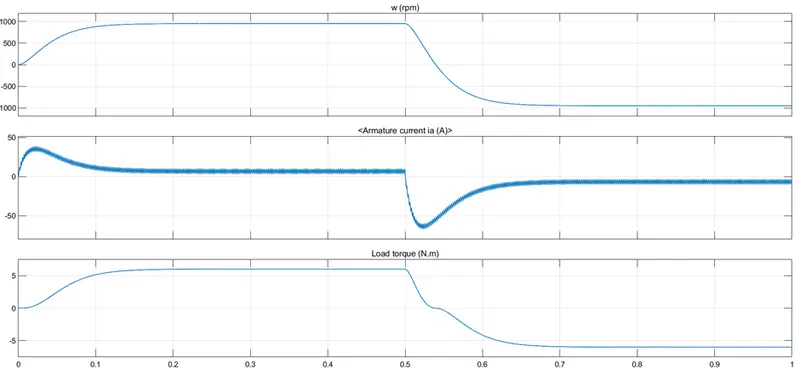
At Starting, Armature Current is high. Later it stabilizes as the Speed and Load Toque stabilizes. After 0.5 seconds, As the Current direction is switched to opposite direction, The Speed and Torque direction also changes. The Current shoots up and gradually stabilizes as the Speed and Torque stabilizes. After 0.5 seconds again change in Current direction occurs and the Cycle repeats.
The Current shoot up is due to the High Speed and High Torque at the time of Direction Switching of the Motor. To achieve the Speed and Torque, The Current shoots up.
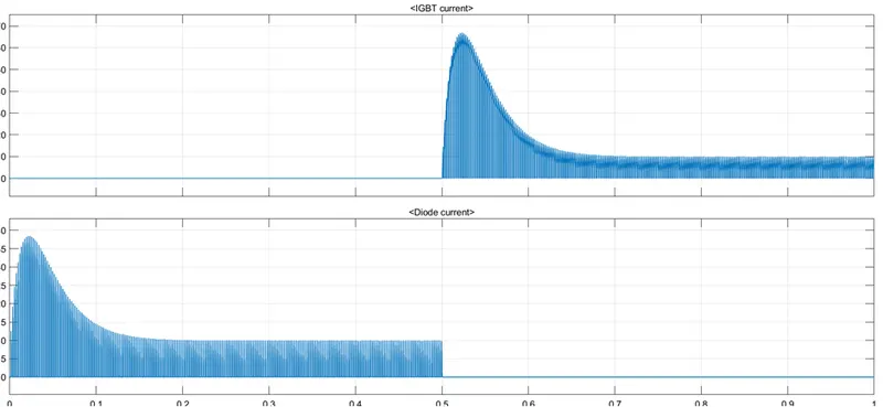
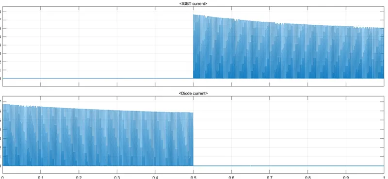
This is the Output Plot of Current flowing through IGBT Q3 and Diode D3. Initially for 0.5 seconds, Q1 and Q4 are turned ON and Q2 nad Q3 are in OFF State. Hence No Current flows through Q3. The Diode D3 provides a path to discharge Energy in the Inductor. When Q3 is turned ON after 0.5 seconds Current flows through Q3.
Controlling the Shoot-Up Current:
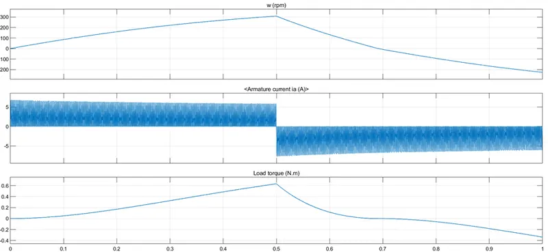
By reducing the Duty Cycle to 40%, The Applied Voltage is reduced which in turn reduces the Speed and Torque of the Motor. Due to this When the Motor is start and When it changes direction, The Starting Current drawn by the DC Motor is reduced.
The Shoot-Out of Current is controlled by reducing the applied Voltage.
2.Four Quadrant Chopper
Four Quadrant Chopper circuit can operate the DC Motor in all 4 Quadrants – Forward Motoring, Forward Braking, Reverse Motoring and Reverse Braking
Simulink Model:
Model Description:
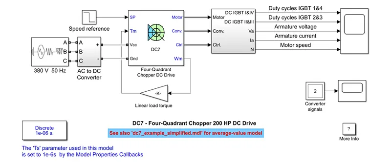
An AC 380V 50Hz source is used as Power Supply. The AC Supply is converted into DC using an AC to DC Converter. The DC Supply is given to Four-Quadrant DC Chopper.
A Speed Reference which is Step Input is also given as Input to the DC Drive. The Step Input initially has a value of 500 and after 2 seconds the Value changes to -1184. The Speed Ramp is set as 400 RPM per second in the DC Drive.
The Speed of the DC Motor is proportional to the Load Torque and it is given as feedback to the DC Drive.
Model Output:
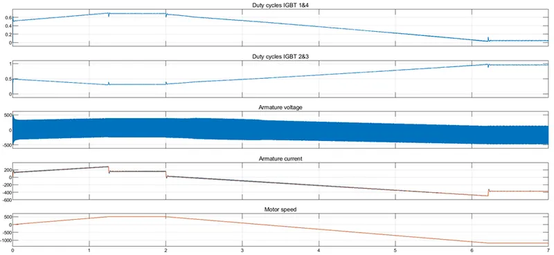
Initially the Motor speed is set to 500 rpm. As per the Acceleration set in DC Drive, The Speed is achieved after 1.25 seconds. The Armature Current stabilizes after the speed is achieved. After 2 secs, The Speed Input is changed to -1184. Now the Duty Cycle of IGBT 1&4 is reduced while the Duty cycle of IGBT 2&3 is increased. Armature Current becomes negative and Voltage applied in mostly negative.
Comparison between 4-Quadrant Chopper DC Drive and H-Bridge DC Drive:
|
4-Quadrant Chopper DC Drive |
H-Bridge DC Drive |
|
Complex |
Simple |
|
Uses PI Regulator (Speed and Voltage Regulator) |
No PI Regulator |
|
Snubber RC Circuit is required |
Snubber RC Circuit is not required |
|
Four Quadrant Operation – Forward Motoring, Forward Braking, Reverse Motoring and Reverse Braking |
Two Quadrant Operation – Forward Motoring and Reverse Motoring |
|
Regenerative Braking is possible |
No Regenerative Braking |
|
Efficiency is High |
Efficiency is Low |
|
Used in Automobile Applications |
Used in Robotics Applications |
2. Develop a 2-quadrant chopper using simulink & explain the working of the same with the relevant results.
Chopper:
Chopper Circuits are DC to DC Converters which converts fixed DC Voltage into Variable DC Voltage.
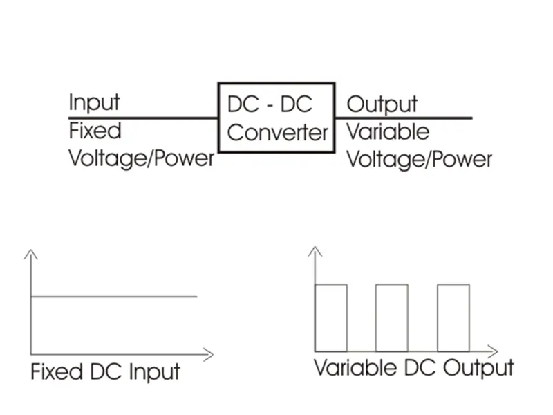
A Chopper Circuit can be designed with variable semiconductive devices such a MOSFET, Thyristor or IGBT based on its applications.
A Chopper Circuit is always designed with a Diode to provide pathway for Reverse Current.
During sudden switching OFF of the Chopper, An Inductive Load can produce sudden Reverse Voltage Spike which can damage the Switching Device. To protect from this Snubber Circuits are used.
Based on its configuration, Choppers Circuits are classified as Types A, B, C, D and E.
- Type A Chopper – Single Quadrant Operation – 1st Quadrant – Voltage and Current are Positive
- Type B Chopper – Single Quadrant Operation– 2nd Quadrant – Voltage is Positive and Current is negative
- Type C Chopper – Two Quadrant Operation – 1st and 2nd Quadrant
- Type D Chopper - Two Quadrant Operation – 1st and 4th Quadrant
- Type E Chopper – Four Quadrant Operation -
Two Quadrant Chopper:
Two Quadrant Chopper uses two Switching devices. It can be in two configurations based on Quadrants in which it needs to operated.
Type-C Chopper:
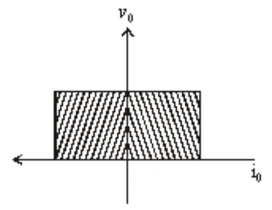
Type-C Chopper works in First and Second Quadrant. In this, Type A and Type B Choppers are connected in parallel.
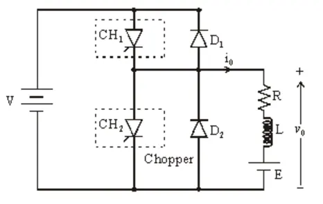
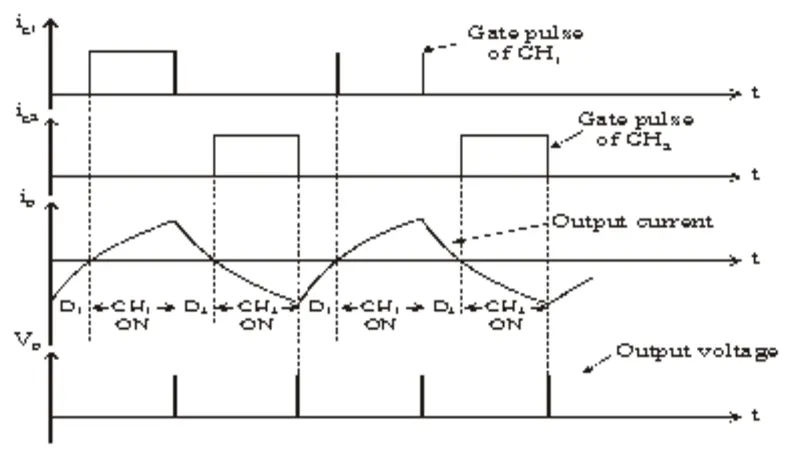
In this configuration, both Switches are Turned ON and OFF alternatively. Both Switches should not be turned ON simultaneously as it causes Short Circuit. When the Switch is OFF, its respective Diode conducts.
The Output Voltage is always Positive.
This type of Chopper is used for Motoring and Regenerative Braking.
Simulink Model of Type-C Model:
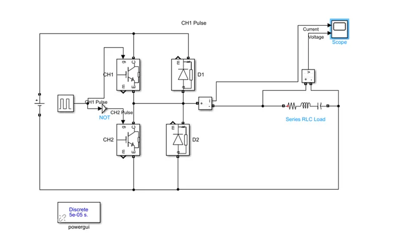
Simulink Model Description:
- Two IGBT Blocks are used as Chopper Switches
- Two Diode Blocks are used to act as Freewheeling Diode
- A Series RLC Load Block is used as Load
- Pulse Generator block is used to supply Gate signal to the IGBT
- As both IGBT must not be Turned ON simultaneously, To work alternatively Complement of the Pulse Generator signal is given as Gate signal to CH2
- A DC Voltage Source block is used to supply 100V supply.
- Current and Voltage are measured using Current and Voltage sensor.
- As ‘Specializes Power System’ blocks are used ‘PowerGUI’ block is used.
Simulink Output:
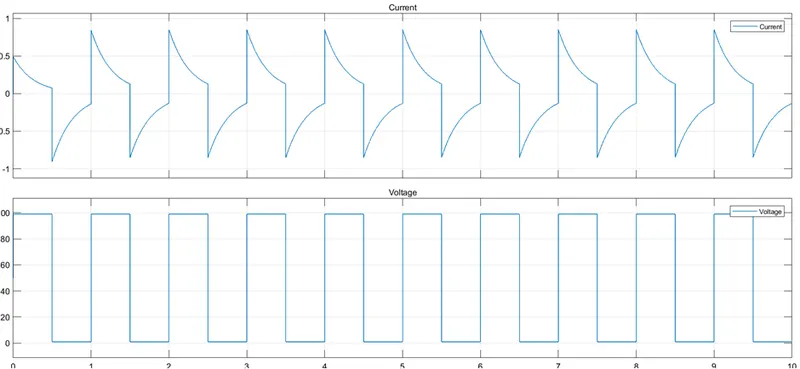
The Voltage always remains Positive.
When the Switch CH1 is turned ON, CH1 and D2 conducts. The Current flows from Source to Load. Hence the Current is Positive.
When Switch CH2 is turned ON, CH2 and D2 conducts. The Current flows from Load to Source. As the Current flows in Reverse direction, Current is Negative.
As explained earlier, The Operation of Type-C Chopper is in 1st and 2nd Quadrant.
Type-D Chopper:
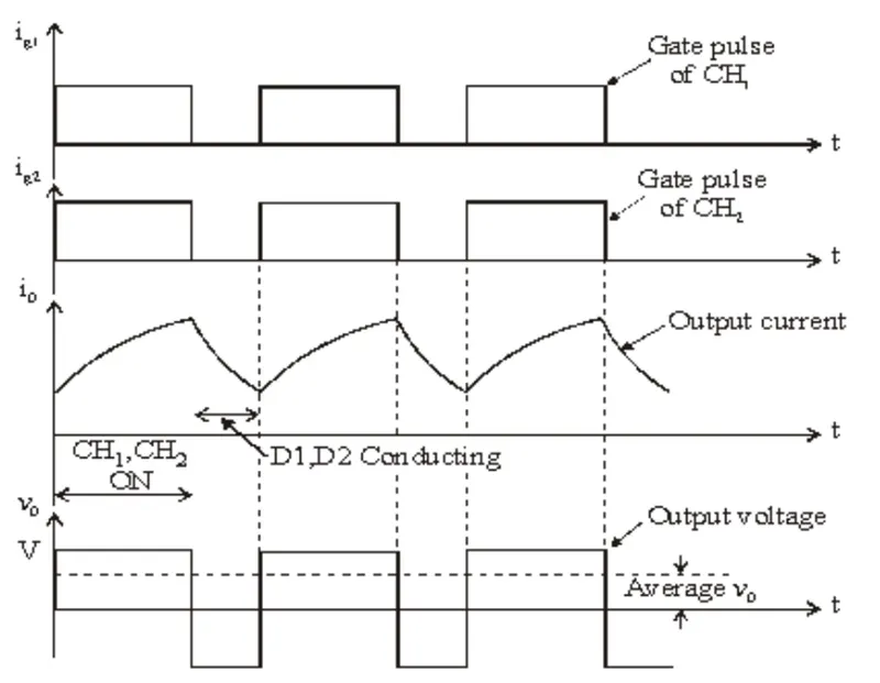
Type-D Chopper works in First and Fourth Quadrant. In this configuration, both Switches are turned ON and OFF simultaneously. When the Switch is OFF, The Diodes conduct.
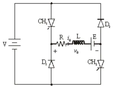
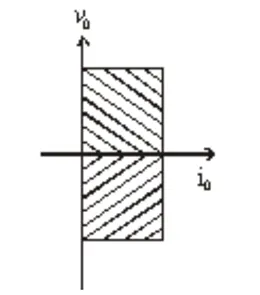
When both Switches are ON, Voltage at Load is positive and equal to Source Voltage. When Voltage at Load is negative, both switches are turned OFF.
The Current is always Positive. As the diodes and choppers conduct current only in one direction the direction of load current will be always positive.
When Switch ON time (Ton) is greater than Switch OFF time (Toff), The Load Voltage is Positive. And vice versa.
SIMULATION MODEL:
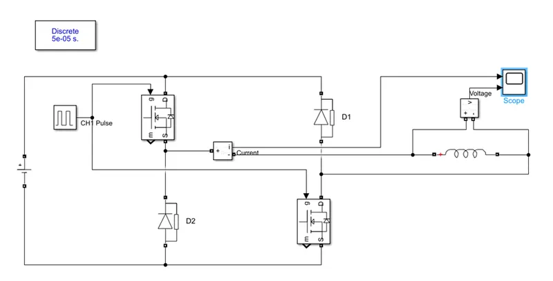
Simulink Model Description:
- Two Mosfet Blocks are used as Chopper Switches
- Two Diode Blocks are used to act as Freewheeling Diode
- A Series RLC Branch Block with Brach Type as Inductive is used as Load
- Pulse Generator block is used to supply Gate signal to both the IGBTs
- A DC Voltage Source block is used to supply 100V supply.
- Current and Voltage are measured using Current and Voltage sensor.
- As ‘Specializes Power System’ blocks are used ‘PowerGUI’ block is used.
SIMULATION OUTPUT:
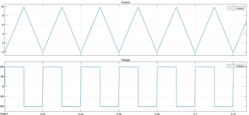
Current is always positive.
When both Switches are ON, The Source is connected to the Load. The Inductive Load gets charged by the Current. Voltage is Positive.
When both Switches are OFF, Conduction takes place through the Freewheeling Diodes. The Stored Energy of the Inductor is dissipated. Voltage is Negative.
As explained earlier, Type-D Chopper works in 1st and 4th Quadrant.
- Explain in a brief about operation of BLDC motor.
BLDC Motor:
Brushless DC Motors are DC Motors with Permanent Magnet in their Rotor and Windings in their Stator. As No Windings are there in Rotor and No need to supply DC Power to the Rotor, No Brushes are used. But In order to Start and Rotate the DC Motor, the direction of the Field generated must be continuously changed. To do that, An Electronic Commutator made of Semiconductive devices is used.
The Electronic Commutator is a DC Drive which controls the Magnitude and Direction of the Voltage to control the Speed and Direction of rotation of the Motor.
Construction of BLDC Motor:
A BLDC Motor construction has similarity between an Induction Motor and a Brushed DC Motor. It has Winding in the Stator and Permanent Magnet in the Rotor. The BLDC Motor doesn’t have Brushes (Mechanical Commutation) in its construction.
Permanent Magnets are installed on the Rotor. Number of Pole pairs depends on Application and Design.
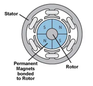
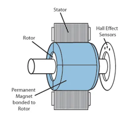
Stator has Windings. It can be Single, Double or Three Phase. Most commonly it is Three Phase.
Position Sensors play a major role in BLDC Motors. The Rotor position is constantly fed back to the controller to do Electronic Commutation. The Stator Winding energized is appropriately altered to keep the Motor running in the Direction. Hall Sensors are used.
BLDC Motor cannot be run without a DC Drive. Electronic Commutation to continuously change the Field is provided by the DC Drive only.
Working of BLDC Motor:
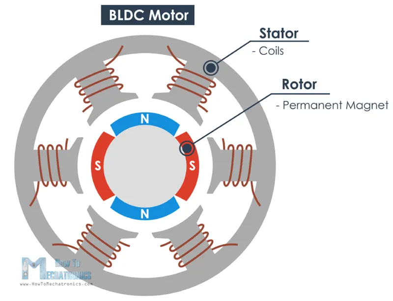
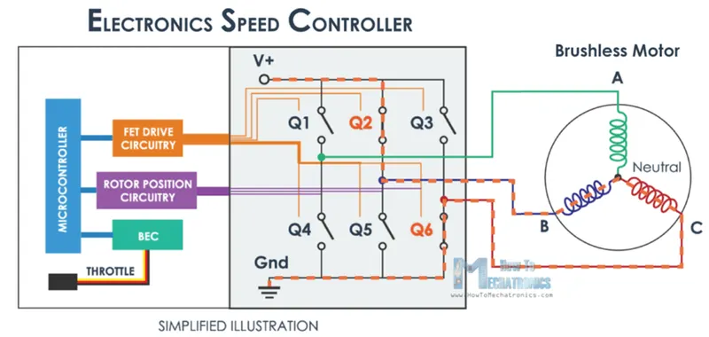
In BLDC Motor, The Permanent Magnet in the Motor aligns itself with Field generated by the Windings of the Stator. When the Rotor is about reach the alignment, The Applied Voltage is switched such that the Rotor PM tries to align with the next Stator Winding Pole. This keeps on to continue to run the Motor in a direction.
Speed-Torque Characteristics of BLDC Motor:
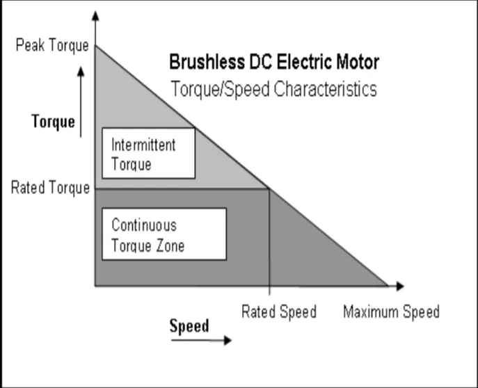
Up to Rated Speed the Torque remains constant at rated Torque. Above rated speed, The Torque falls.
CONCLUSION:
Thus, MATLAB Model ‘Speed control of a DC motor using BJT H-bridge’ is studied and compared with ‘The Four-Quadrant Chopper DC Drive (DC7) block’.
A 2-Quadrant Chopper Model is created using Simulink.
Operation of BLDC Motor is studied.