Week -2
SIMULINK MODEL OF DOOR BELL USING SOLENOID BLOCK
OBJECTIVE:
To make a Simulation Block of Door Bell using Solenoid Block based on the given arrangement and to create a situation where the Switch is closed for 2 seconds and then released.
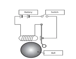
SIMULATION MODEL:
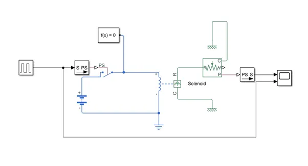
BLOCKS USED IN THE SIMULATION MODEL:
- Pulse – To control the operation of the Switch ON and OFF function
- Simulink-PS Converter – To change the Simulink Signal from the Pulse Block to Physical Signal that can control the Switch
- Switch – To perform the Switching Operation based on the Physical Signal
- Battery – To supply Power
- Solver Configuration – Defines solver settings to use for the Simulation.
- Electrical Reference Port – When using Electrical Signals in a model, the Model must contain an Electrical reference port.
- Solenoid – Converts the Electrical Supply to Mechanical motion by moving the Plunger.
- Ideal Translational Motion Sensor – Measures the Mechanical Motion and converts into proportional control signal (PS).
- Mechanical Translational Reference Point – When Translational Motion is involved in a model, The Model must contain a Mechanical Translational Reference Point
- PS-Simulink Converter – To convert the Control Signal (PS) into Simulink Signal
- Scope – To plot the Signal
OUTPUT:
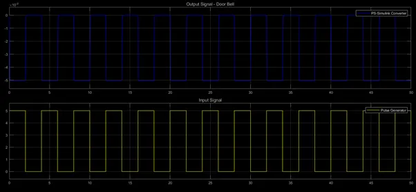
INFERENCE:
The Switch is closed for 2 seconds. The Solenoid coil is activated and the Plunger moves to the negative position and stays there for 2 seconds. When Switch is opened, The Solenoid coil is de-energised and the comes to rest position.
Increasing the No. of Pulses per second (Period of a Pulse < 0.01 seconds) will move the plunger rapidly and give a continuous bell sound similar to an Actual Bell.
CONCLUSION:
Thus a Simulation Model of Door Bell using Solenoid Block is made and the Physical Movement of the Plunger is plotted.
SIMULINK MODEL OF A HEATER FAN CONTROLLED BY A THERMISTOR
OBJECTIVE:
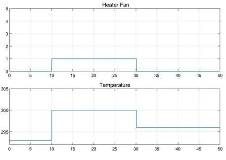
To Use a Thermistor to sense the temperature of a heater & turn on or turn off the fan the given conditions.
- Temperature source: 20 °C from 0 to 10 seconds, 27 °C from 10 to 30 seconds, 23 °C from 30 to 50 seconds
- Fan conditions: ON if the temperature above 25 °C, OFF otherwise
SIMULINK MODEL:
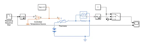
SIMULINK BLOCKS USED:
- Repeating Sequence Stair – To give input to the System in Discrete Time Sequence
- Controlled Temperature Source – Ideal Energy Source in a Thermal Network
- Thermistor – This Block represents NTC Thermistor
- Voltage Sensor – Measures Voltage and converts it into proportional Physical Signal
- Switch – Toggles between two Inputs based on the Condition
DESCRIPTION OF THE SIMULINK MODEL:
The Given Source Temperatures are updated as Discrete Values through Repeating Sequence Stair Block. With those Values as Input, Controlled Temperature Source maintains the Temperature. The Thermistor senses the Temperature. The Voltage across the Resistor in series is measured and based on its proportional physical signal, Fan is turned ON and OFF.
SIMULINK OUTPUT:
CONCLUSION:
Thus, The Simulink Model to use a Thermistor to sense the Temperature of a Heater and Turn ON or OFF the Fan based on the conditions is modeled and the Output is plotted.