Project
SYSTEM LEVEL SIMULATION OF BAJA ATV
OBJECTIVE:
To Carry out a system-level simulation of an all-terrain vehicle (MATLAB BAJA ATV Model) and to Prepare a technical report explaining the model properties & comments on the results.
ALL TERRAIN VEHICLE (ATV):
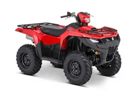
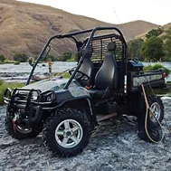
ATV means an All-Terrain Vehicle which is specially designed for an off road driving with very rough terrain, jumps, maneuverability and endurance. An all-terrain vehicle (ATV) is defined as a motorized off-highway vehicle designed to travel on four low-pressure or non-pneumatic tires, having a seat designed to be straddled by the operator and handlebars for steering control.
CONTINUOUSLY VRIABLE TRANSMISSION (CVT):
The said BAJA ATV Model uses Continuously Variable Transmission (CVT).
A CVT, or continuously variable transmission, seamlessly changes through an unending range of effective gear ratios while you drive, whereas other kinds of mechanical transmissions offer a fixed number of gear ratios and have hard shifts between each.
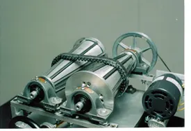
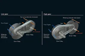
While a traditional transmission uses a wide variety of intricate parts to shift between a range of pre-set gears, most CVT systems work through a pulley system. In short, this system consists of cones at each pulley connected via a chain belt. The cones can move to increase or decrease the belt diameter to change gear ratios, allow for quick shifting into the needed ratio for increased power, and boost fuel economy
SIMULATION MODEL:
Engine Sensor:
CVT:
VEHICLE BODY:
MODEL DESCRIPTION:
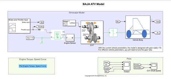
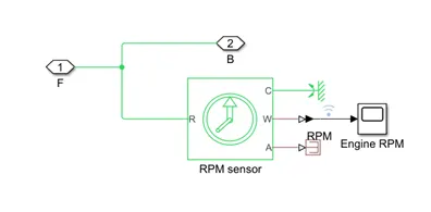
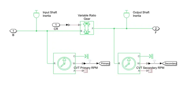
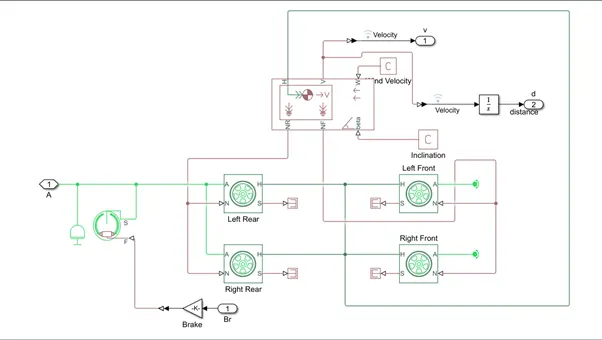
The Input for the Model (Throttle and Brake) are given by using Signal Generator.The Throttle signal is converted into proportional Angular Velocity using ‘Generic Engine’ block. The Angular Velocity is measured into RPM signal using ‘Ideal Rotational Motion Sensor’. The Angular Velocity is given as input to Continuous Variable Transmission (Masked Sub-system). With reference to the ‘cvtRatio’ given using the Signal Generator, ‘Variable Gear Ratio’ Block change the gear ratio and thereby changing the Speed. Input and Out RPM are measured using ‘Ideal Rotational Motion Sensor’ Block. The Rotational Signal is taken through a Simple Gear and given as Input to the ‘Vehicle Body’ masked sub-system. The Angular Velocity is given to the 4 Tires. The Translational Motion from the Tires is given as input to ‘Vehicle Body’ Block. The Vehicle Properties such as Mass, Dimensions etc are preset in the Block. Wind Speed and Inclination is given as constant signals to the block. From the Values, the ‘Vehicle Body’ gives the Normal Force signal to Tires. It also gives out the Actual Velocity of the Vehicl and its integrated value gives the Distance Covered.
CASE 1: Brake=0; Constant Throttle; CVT Ratio given by Signal Builder
INPUT SIGNAL:
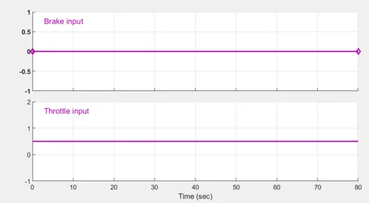
Brake Input is kept Zero (No Brake Applied) and a Constant Throttle of 0.5 is applied.
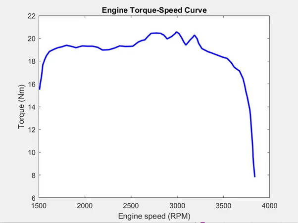
The Torque is around 18-20Nm between 1600-3500 and above that the Torque falls rapidly and max possible speed is 3700 RPM.
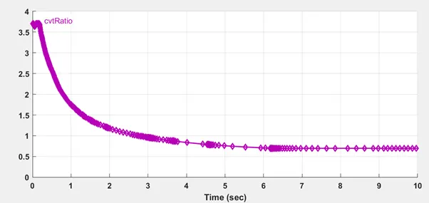
The CVT Gear Ratio is increased as the vehicle goes on from 3.7(approx.) to 0.7(approx.)
OUTPUT:
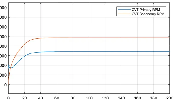
With respect the CVT Ratio applied, Primary and Secondary RPM of CVT varies. Initially (for 3 sec approx.) the Secondary RPM is less than the Primary, then it is higher and stabilises as a constant throttle is applied.
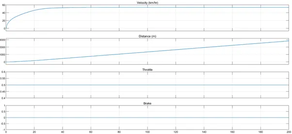
The Resultant Vehicle Velocity is calculated by the ‘Vehicle Body’ block based on the Inputs. Vehicle RPM is proportional to CVT secondary rpm.
The Distance Covered linearly increases.
Throttle and Brake Input remains constant.
CASE 2: Brake=0; Throttle=1; CVT Ratio given by Lookup Table
SIMULINK MODEL:
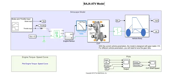
CVT Ratio is set as per the Lookup Table which is a plot between Speed and CVT Ratio
INPUT SIGNAL:
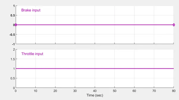
A Constant Throttle (=1) is applied and No Braking.
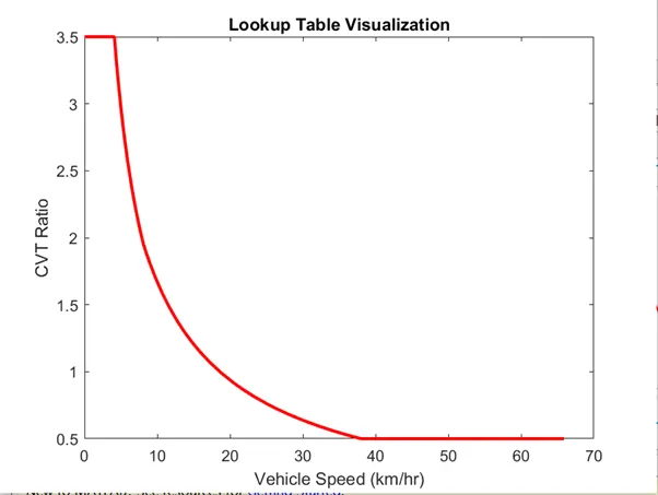
The Lookup Table is the relation between Speed and CVT Ration. This is given as reference for the CVT Sub-system to assign CVT Ratio values. After 17.5Km/h, CVT Ratio reduces below 1.
OUTPUT:
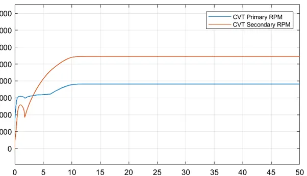
When the Vehicle speed is above 17.5Km/h, CVT Ratio is reduced below One. Hence the Secondary RPM becomes higher than Primary RPM.
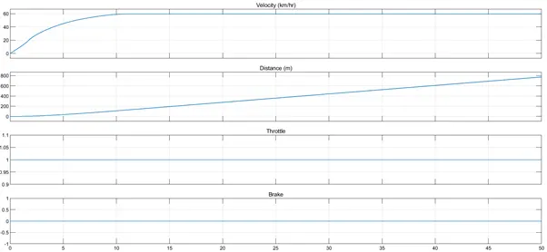
As the Throttle is constant and No Brake applied, Velocity increases and becomes stable. The Distance covered linearly increases.
CASE 3: Closed Loop Model with Dashboard
SIMULINK MODEL:
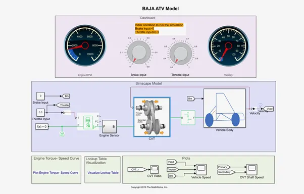
The Model is a Closed Loop Model. The CVT Ratio is varied with respect to Vehicle Speed based on the Lookup Table. Throttle and Brake are controlled using the Dashboard.
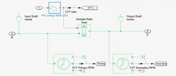
The CVT Ratio is set with reference to Vehicle Speed based on the Lookup table.
OUTPUT:
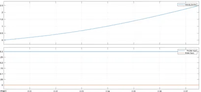
Initially As the Throttle is applied, Vehicle Speed Gradually increases.
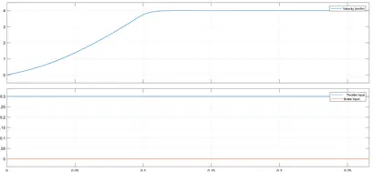
And the Velocity stabilises around 4 Kmph.
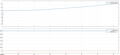
But as the Model is a closed loop model, Though the Throttle is kept same, with respect to the Vehicle Speed the Gear Ratio is constantly varied which in turn increases the Speed and the loop continues.
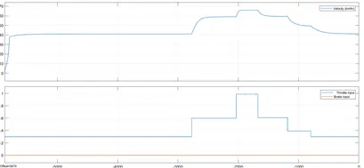
Once the Minimum possible CVT Ratio (0.5) is reached, For the constant throttle Vehicle Velocity stabilises and remains constant. Then As the Throttle input is varied, Vehicle Speed varies proportionately.
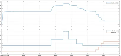
When the Brake is applied The Vehicle speed reduces proportionately.
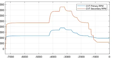
As the CVT Ratio is varied, the Primary and Secondary RPM varies proportionately. When the Velocity is above 17.5 Kmph, CVT Ratio becomes less than one and Viceversa.
CASE 4: Throttle, Brake and CVT Ratio through Signal Builder
INPUT:
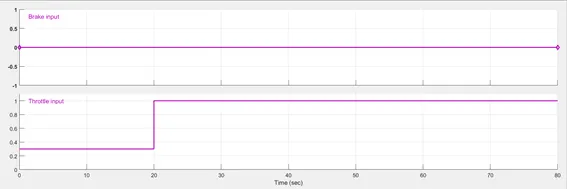
Throttle is a Step Signal. For 20 sec it is 0.3 and then increased to 1; No Braking (=0)
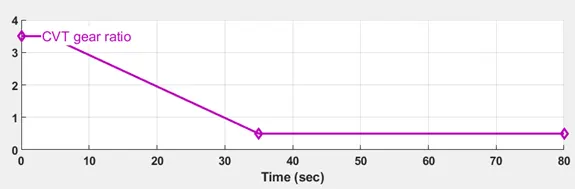
CVT Ratio becomes less than 1 at 30 secs and stabilises at 0.5 after 35 secs.
OUTPUT:
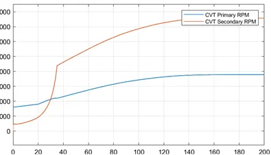
Secondary RPM becomes higher than the Primary RPM after 30 secs as the CVT Ratio becomes less that one. The Rapid increase of Secondary RPM slows down into gradual increase after 35 secs as the CVT Ratio stabilises to 0.5
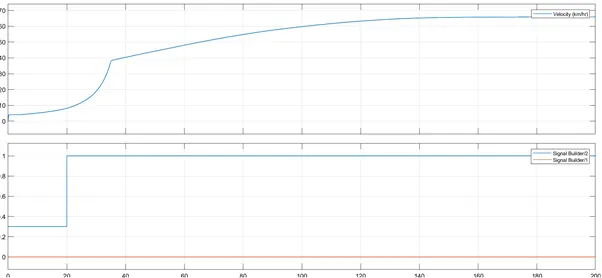
After 20 sec, Throttle is increases to 1. The CVT Ratio stabilises at 0.5 after 35 secs. Hence after that the Velocity gradually increases and starts to stabilise.
CASE 5: Closed Loop Model with Step Signal as Input for Throttle
INPUT:
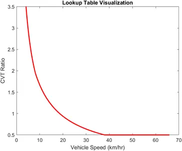
The CVT Ratio becomes less than 1 around 18kmph and stabilises to 0.5 near 38kmph.
OUTPUT:
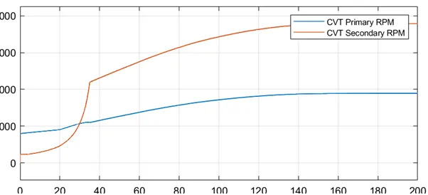
Secondary RPM becomes higher than Primary RPM after 18kmph (near 30 sec)
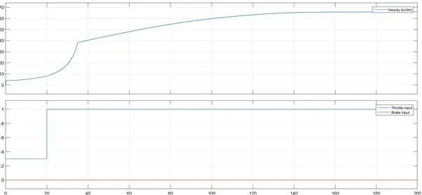
As the CVT Ratio and Throttle becomes constant, The Rapid increase in velocity decreases and starts to increase gradually and stabilises.
CONCLUSION:
Thus, the System Level Simulation of an All-Terrain Vehicle was carried out and Technical report explaining the Model properties and its results are commented.