Week - 4
CONTROL LOGIC OF ‘WASHING MACHINE’ USING STATEFLOW
OBJECTIVE:
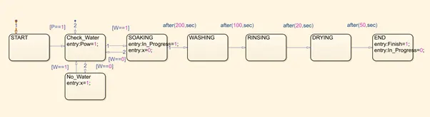
To implement control logic of a “washing machine” using Stateflow as per given sequence
- If the power supply is available, the system gets activated
- If the Water supply is not available, stop the process & indicate through LED
- Soaking time should be 200s followed by Washing time of 100s.
- Then rinsing happens for next 20s & dryer runs for 50s
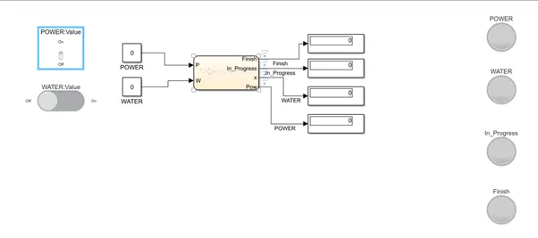
SIMULINK MODEL:
STATEFLOW DIAGRAM:
DESCRIPTION:
Power and Water Values are given as Input to the State Machine. Initial State Transition conditions are based on Power and Water Values. If the condition is true, Transition to next states takes place. Later state transitions are based on Time conditions. Inputs and Outputs of the Chart (State Machine) is added through ‘Add Inputs and Outputs’ option.
SIMULINK MODEL OUTPUT:
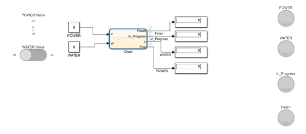
- No Power
- When Power=0, The Condition fails at 1st State itself. No State transition occurs and no further progress.
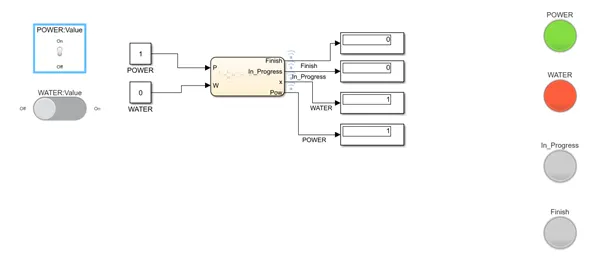
- Power=1 & No Water
- As Power=1, The 1st Condition is satisfied and state transition to next state occurs. But as the next condition is failed, No_Water state is executed.
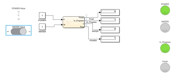
- Power=1 & Water=1 (During Process)
As Power=1 and Water=1, Next Condition is satisfied and further states are executed as per the Control Logic of Time Period
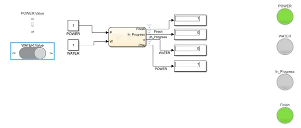
- Power=1 & Water=1 (FINISH)
After all states are executed, The Last State returs ‘Finish’ value as 1.
CONCLUSION:
Thus, The State flow Model to implement the Control Logic of a Washing Machine is implemented.
Simulink chart for the “Gear shift” logic
OBJECTIVE:
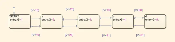
To Make a Simulink chart for the “Gear shift” logic as per below conditions
Speed Range(kmph) Gear
0 to 15 1
16 to 25 2
26 to 40 3
41 to 60 4
Above 61 5
Give speed input while the simulation is running & display the gear number.
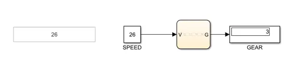
SIMULINK MODEL:
STATEFLOW CHART:
DESCRIPTION:
Control Logic is set based on Speed – Gear Relation. If the Control Logic satisfies, State Transition takes place and its equivalent Gear value is given as Output.
SIMULATION OUTPUT:
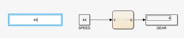
- Speed=44 Kmph
As per the Speed Value, Based on Control Logic 4th State is executed.
- Speed = 59 Kmph
As per the Speed Value, Based on Control Logic 5th State is executed.

- Speed = 23 Kmph
As per the Speed Value, Based on Control Logic 2nd State is executed.

CONCLUSION:
Thus, A Simulink Chart for the ‘Gear Shift’ logic as per the given conditions is made.