Week-7 Challenge: DC Motor Control
(1a) AIM- Explanation Of The MATLAB Model "Speed control of a DC motor using BJT H-bridge".
MODEL- To open the Model in your MATLAB, enter the "power_Hbridge" in your Command Window.
EXPLANATION-
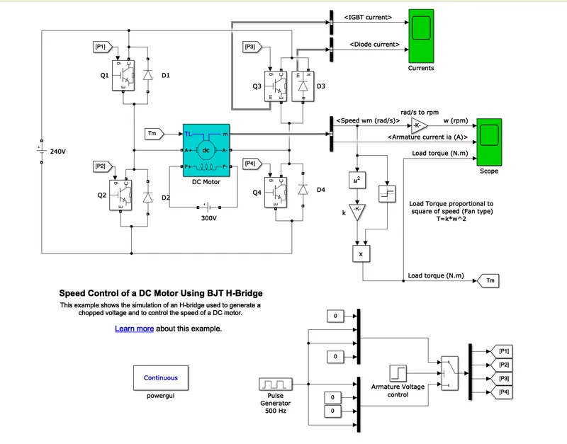
- Here the "DC Machine" block is used as a load, connected between the H-bridge arrangement of power electronics switches("BJT") with antiparallel "DIODE".
- `T_L` is a torque input to the shaft of the machine and (A+, A-) are the armature circuit.
- (F+, F−) are the field terminals for the wound-field DC machine, so that the machine model can be used as a shunt-connected or a series-connected DC machine.
- The output of the block is a vector containing measurement signals(m).
- The Bipolar Junction Transistor (BJT) when used for power switching applications, operates as an IGBT. So the block used is "IGBT" as a switch.
- Here the Model is constructed in such a way that the motor doesn't operate in the braking mode. This drive Model is used for Forward Motoring and Reverse Motoring.
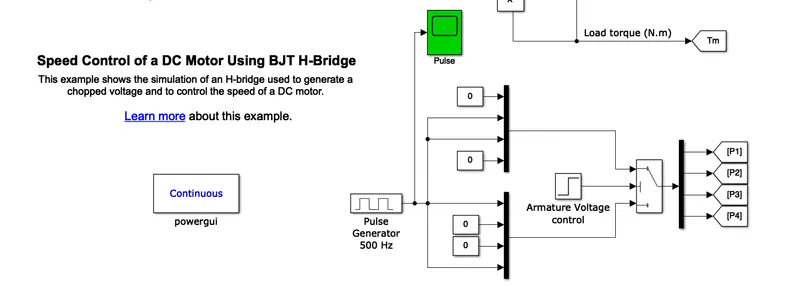
- For providing the signal to the switches, an arrangement is done as Q1 & Q4 operates with a positive voltage at a time and Q2 & Q3 conducts after that with negative voltage. You can see the arrangement as below:-
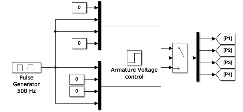
For creating a signal "Pulse Generator" is used and given to the "Mux" with the other 3 inputs as shown above.
Two sets of Mux and Armature Voltage with 0.5 step time are given to switch. If armature voltage is greater or equal to the threshold of the switch then Upper Mux is passed which will activate Q2 & Q3 and else lower Mux is passed which will activate Q1 & Q4. - These signals are applied to the switches by using the "Goto" and "From" blocks.
- Measurement Port for Switch and Diode is available as an option, which will be used to see the Voltage and Current passing through it.
- The "Bus Selector" block is used to select the parameters of it and the "Scope" is connected with the output of the "Bus Selector" block to plot the graph.
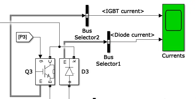
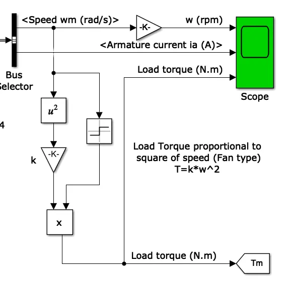
- A similar "Bus Selector" is used for getting "DC Machine" parameters like speed, armature current, field current, electrical torque. Here in this model only speed(rad/s) and armature current ia(A) are taken as an output.
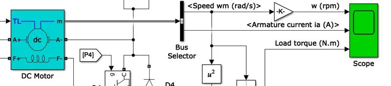
- From the known formula of torque as `T=Kw^2`, torque is also given to the "Scope" block.
- And finally a "Powergui" block is placed at the top-level diagram of the model. It decides the method to solve the circuit(option are given to the user).
One need the Powergui block to simulate any Simulink model containing Simscape Electrical Specialized Power Systems blocks.
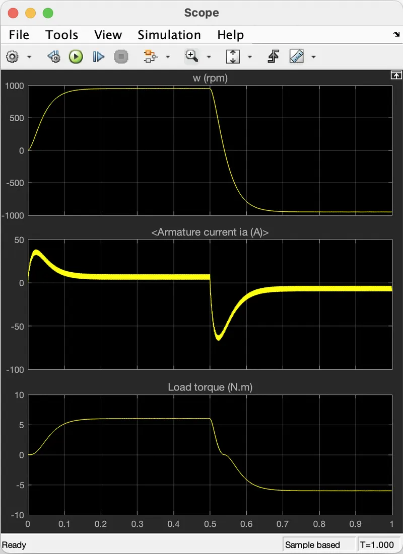
WORKING- When the positive voltage is applied to the DC Motor, it rotates in the forward direction but after 0.5 sec the voltage is negative so that DC Motor runs in the reverse direction. It can be verified by seeing the graph given below
RESULTS-
(i) Motor Parameters:-
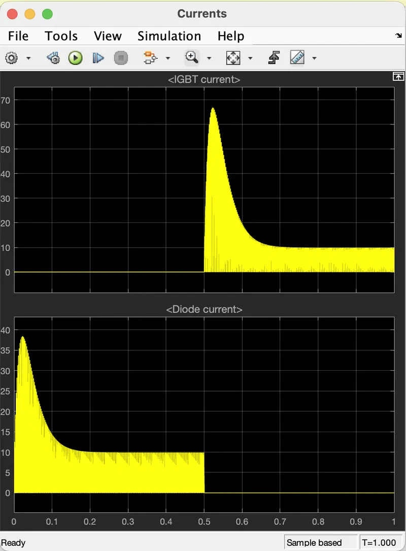
(ii) Switch Current and Diode Current:-
(1b) AIM- Comment On The Armature Current Shoot-Up From The Scope Results.
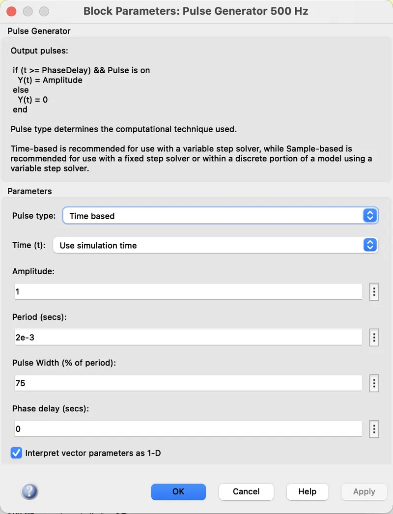
SOLUTION- Case (i) Here set the Pulse width of the "Pulse Generator" block to 75% as shown below:-
Connect the "Scope" block to the "Pulse Generator" to view the signal given to the Switches
After completing the simulation of the Model we get the Input Pulse in the "Scope" block we had connected to the "Pulse Generator", as shown below:-
And the output of Motor Armature Current is as below:-
Here the armature peak current is nearly 40 amps. Due to this high current, the motor winding can be damaged. So for limiting this peak current, we have to reduce the pulse width of the pulse generator.
(i) Speed of the Motor is 1000 rpm
(ii) Armature Current nearly 15 amps.
(iii) Load Torque is 6 Nm.
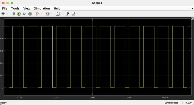
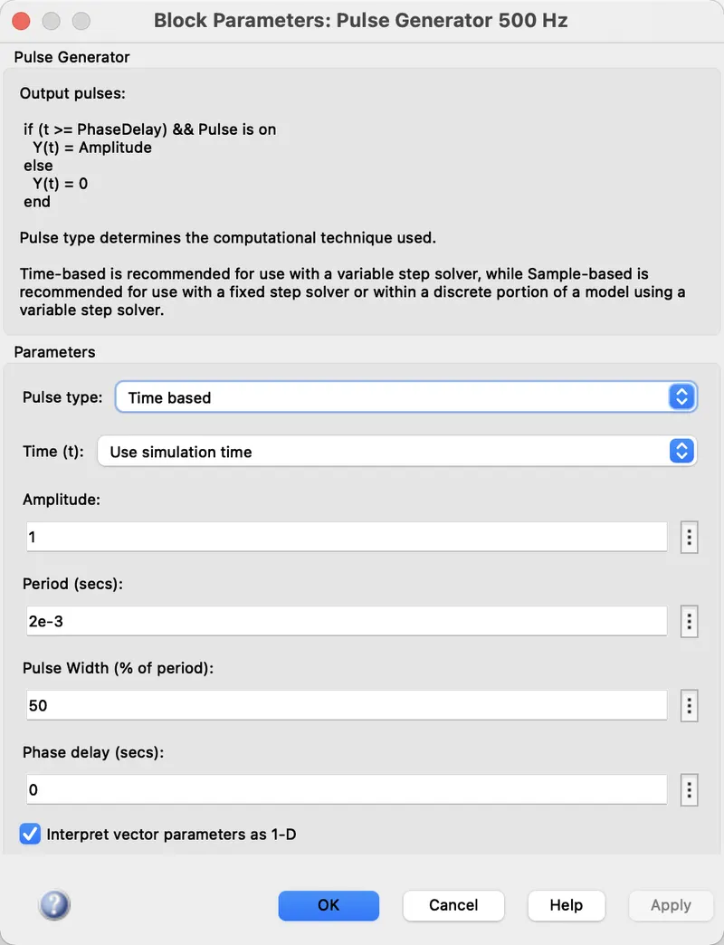
Case (ii) Now set the Pulse width of the "Pulse Generator" block to 50% as shown below:-
After completing the simulation of the Model we get the Input Pulse in the "Scope" block we had connected to the "Pulse Generator", as shown below:-
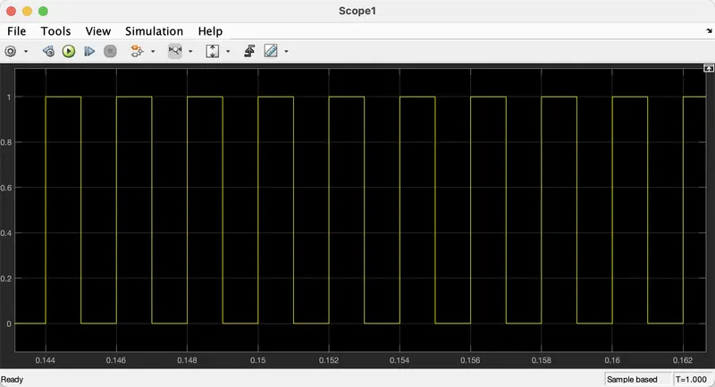
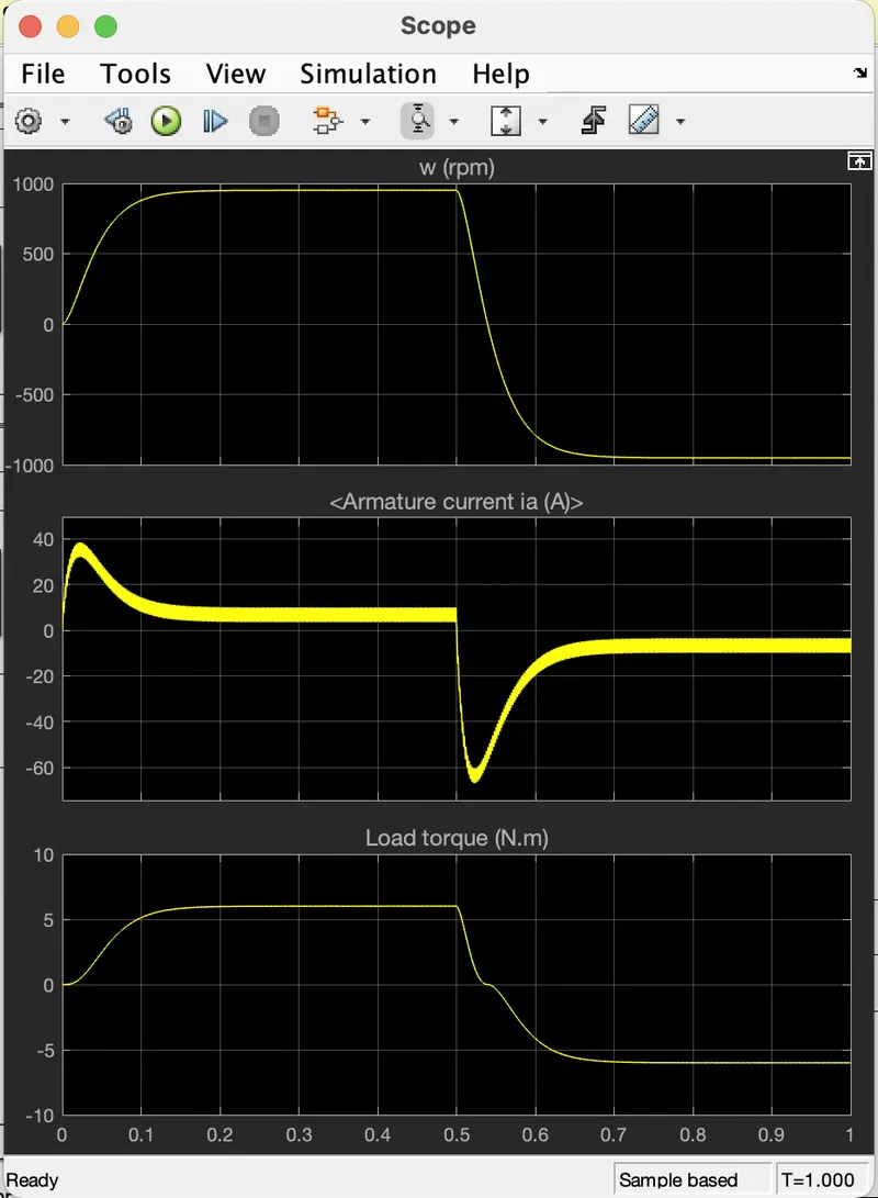
And the output of Motor Armature Current is as below:-
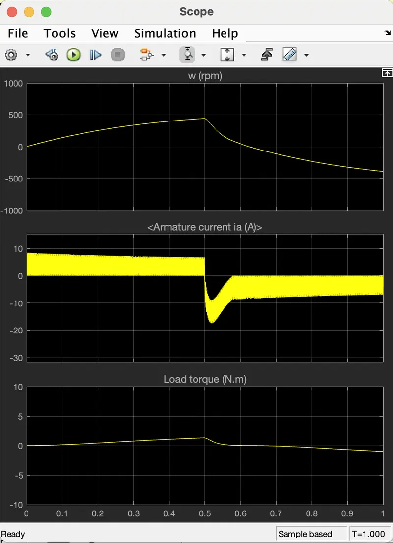
The armature peak current is nearly 8 amps in forward motoring and -18 amps in reverse motoring. Therefore we say that as the pulse width decreases then the peak value of armature current decreases.
(1c) AIM- Compare The ‘The Four-Quadrant Chopper DC Drive (DC7) Block’ With The H-Bridge Model.
SOLUTION- Here the DC Motor is separately excited with a DC field voltage source. The armature voltage is provided by an IGBT converter controlled by two PI regulators. To limit the DC bus voltage during dynamic braking mode, a braking chopper has been connected between the Diode-Rectifier and the DC7 Block.
Now we directly see the points of comparison of BJT and Four-Quadrant Chopper DC Drive.
| Sr.No. | BJT H_Bridge | Four Quadrant Chopper |
| 1 | Two quadrant operation. | Four quadrant operation. |
| 2 | Forward & Reverse Motoring are possible. | Forward & Reverse motoring, Forward & Reverse braking are possible. |
| 3 | Regenerative braking is not possible due to the use of BJT switches. | It is possible, as IGBT switches are used. |
| 4 | Reference speed is not possible, as it is an Open-loop System. | It is possible, as this is a closed-loop system. |
| 5 | Armature current control is not possible as this is an open loop. | It is possible as this is a closed-loop. |
| 6 | The current values are continuous. | The current values are chopped. |
| 7 | Comparatively less efficiency at moderate power levels. | Better efficiency at high power levels. |
(2) AIM- Model The Two-Quadrant Chopper Using Simulink & Explain The Working.
SOLUTION-
Blocks Used:-
(i) MOSFET
(ii) Diode
(iii) DC Motor
(iv) DC Voltage Source
(v) Pulse Generator
(vi) Constant
(vii) Scope
(viii) Powergui
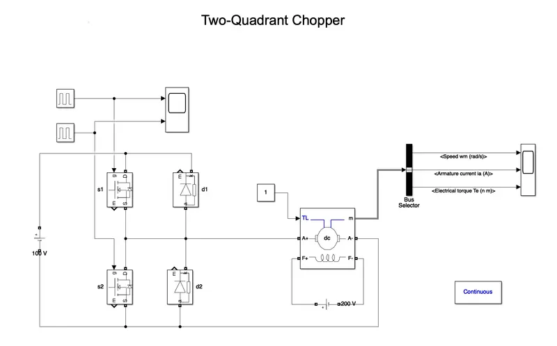
Model:-
WORKING-
1st Quadrant Operation:- When s1 is ON and s2 is OFF, then the positive DC voltage is applied to the Motor. Here the voltage and current both are positive. Hence motor will rotate in a forward direction.
2nd Quadrant Operation:- When s1 is OFF and s2 is ON, then the voltage applied across the motor is positive but the armature current is negative. Hence motor will rotate in forward regenerative mode.
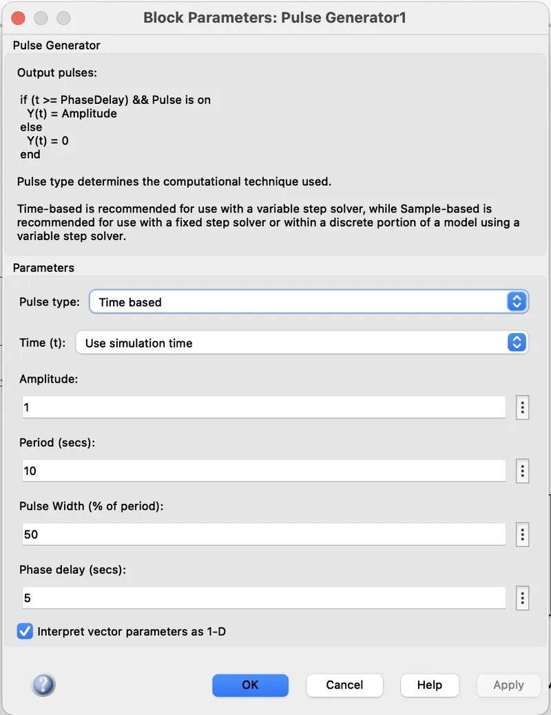
MODELLING- The parameters set for the "Pulse Generator" are shown as below:-
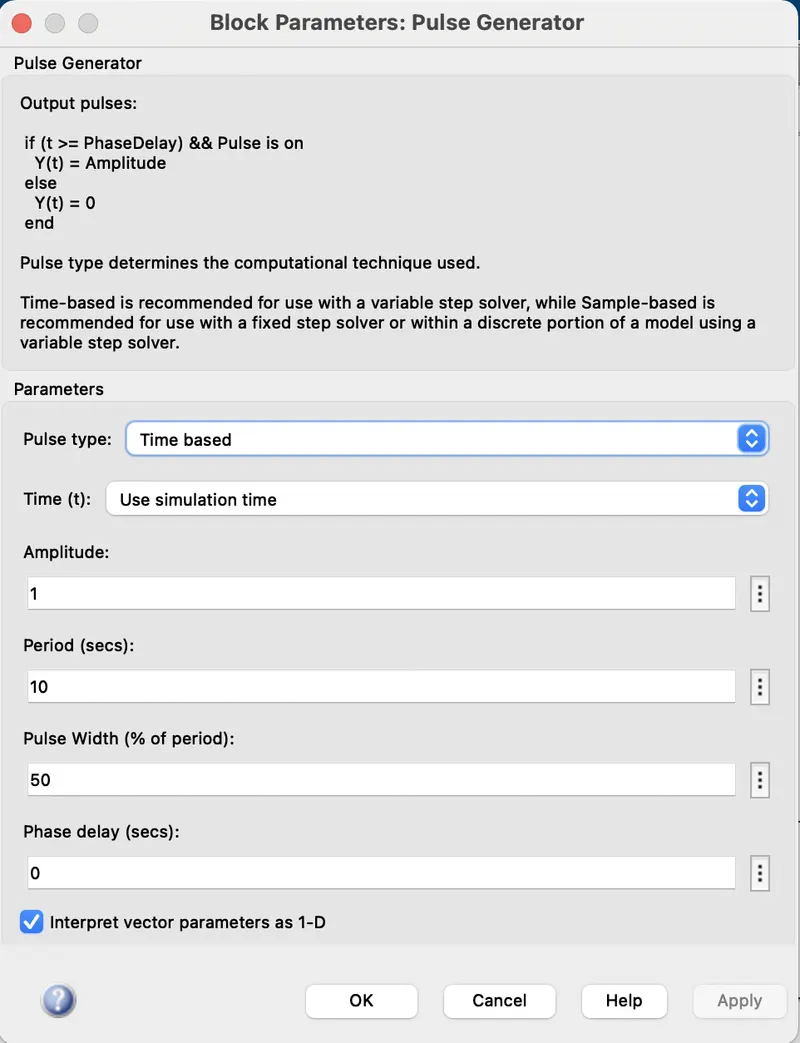
This pulse is applied to the s1 switch.
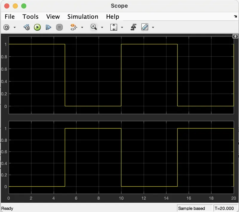
And the pulse with the phase delay of 5 secs is applied to the s2 switch as shown below:-
After simulating the model for 20 secs. We get the pulse results as below:-
RESULTS-
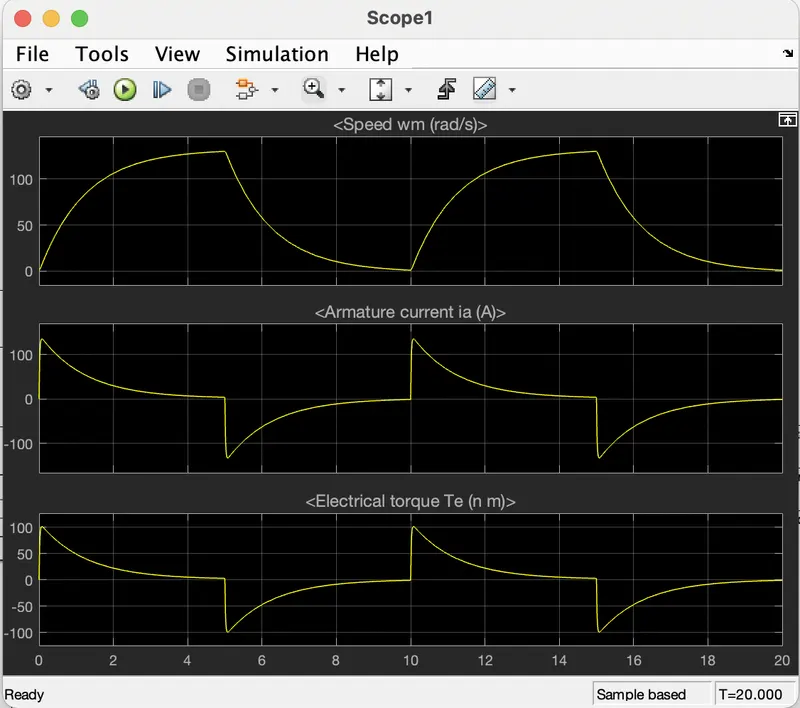
At the time of starting the motor is rotating in forward direction for 5 sec till the switch s1 is conducting with the speed reaches 120 rad/s, armature current is nearly 0.8 amps and torque is nearly 1 Nm.
At t=5 sec s1 is OFF and s2 will be ON, at that time forward regenerative braking is applied and the speed reaches zero.
CONCLUSION-
- Two quadrant chopper DC motor operates in forward motoring and forward braking.
- At starting armature current is nearly 125 amps. This peak current can cause damage to the windings.
- To reduce this starting current, a called starter is used.
(3) AIM- Explain About Operation Of BLDC Motor.
EXPLANATION- Brushless DC Motor is a special kind of permanent magnet synchronous motor.
Current in the DC motor is automatically switched to different windings by means of a commutator and brushes to create continuous motion.
In BLDC motor commutation is implemented electronically with a drive amplifier that uses semiconductor switches to change the current in the windings based on rotor position feedback.
WORKING- The principle BLDC motor is similar to that of a conventional DC motor, i.e., the Lorentz force law which states that whenever a current-carrying conductor is placed in a magnetic field it experiences a force. As a consequence of the reaction force, the magnet will experience an equal and opposite force. In the case of, BLDC motor, the current-carrying conductor is stationary while the permanent magnet moves.
Here the stator coils are electrically switched by a supply source, it becomes an electromagnet and starts producing the uniform field in the air gap. The force of attraction is produced in between the electromagnet stator and permanent magnet rotor, hence the rotor continues to rotate.
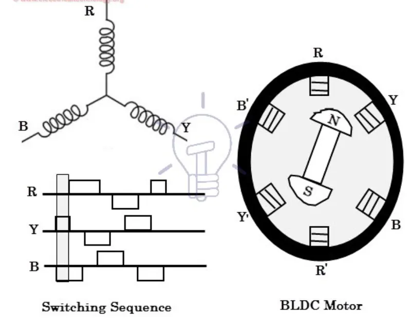
In this type of motor, the motor produces a torque because of the development of attraction force (North-South or South-North) and repulsion force (North-North or South-South).
Here the hall sensors are used for knowing the shaft position. Based on this signal from the sensor, the controller decides particular coils to energize. This is how the BLDC Motor works.