Week-6 Challenge: EV Drivetrain
(1) AIM- Describe the types of power converter circuits that are employed in electric and hybrid electric vehicles.
SOLUTION- Mainly there are four types of power converter circuits used in an electric and hybrid electric vehicle. There are as follow:-
(i) AC to DC Converter
The power electronics converter which is used for converting AC to DC is called a rectifier circuit. In the circuit of an AC to DC converter, there is a step-down transformer, a diode, a capacitor, and a low dropout voltage (LDO) regulator.
The step-down transformer takes the high-level Voltage from the main supply and steps it down to a lower level as per requirement, but it is still in AC form. Then a diode or group of diodes will restrict the current to flow in just one direction. The diode(s) will remove the negative parts of the waveform so that there are positive peaks only. This is called "Rectifying" and this part of the circuit is referred to as a "Rectifier". After that, the output voltage waveform is smoothened by a filter capacitor. Finally, the LDO regulator will regulate the output as per requirements.
In the case of EVs and HEVs, the battery pack which operates with the DC power supply is charged with the AC supply. So, the chargers for these vehicles are an e.g of the AC to DC power converter.
(ii) DC to AC Converter
This power converter is the opposite of the previous one. This will converter the DC power to the AC power using an electronic switch, which is basically a set of semiconductor transistors e.g. IGBTs, MOSFETs.
In EVs and HEVs, the battery will supply the power to the inverter and the inverter will convert it into AC waveform by using its primary and secondary winding of the transform. This power is then given to AC load.
(iii) DC to DC Converter
This type of converter takes the power of DC level 1 and supply it by converting it into DC level 2. This kind of converter is called a "Chopper".
In EVs and HEVs, this type of converter is used for various purposes. e.g. for car radio, lights, Infotainment display, etc.
(iv) AC to AC Converter
AC to AC converters is used for converting the AC waveforms with one particular frequency and magnitude to AC waveform with another frequency at another magnitude. This conversion is mainly required in the case of speed controlling of machines, for low frequency and variable voltage magnitude applications as well. We know that there are different types of loads that work with different types of power supplies like single-phase, three-phase supplies, and the supplies can be differentiated based on the voltage and frequency range also. This kind of converter is known as a cyclo converter.
(2) AIM- To find the speed of the EV car.
GIVEN DATA- (i) Speed-Torque Equation:- `Tv=24.7 + (0.0051)*omega^2`
(ii) Duty Cycle- 70%
(iii) Voltage(V)- 72 V
(iv) Ra= 0.5 Omega
(v) `K*phi= 0.7 Volt Second`
(vi) Chopper Switching Frequency= 400 Hz
SOLUTION- we know that,
the motor equation is:
`omega=v/(Kphi)- (Ra)/(Kphi)^2*T`
rearranging the equation,
`T=(V*Kphi)/(Ra)- (omega*(Kphi)^2)/(Ra)` `implies (1)`
here V is the voltage of the motor, so finding it
from duty cycle i.e 70% of total V
i.e `70/100*72= 50.4 V`
This is motor voltage.
Now substituting all values in (1), we get
`T= (50.4*0.7)/0.5 - (omega*(0.7)^2)/0.5`
`T= 70.56 - 0.98omega` `implies (2)`
Now comparing equation (1) and (2)
`24.7 + (0.0051)*omega^2= 70.56 - 0.98omega`
`0.0051omega^2+ 0.98omega - 45.86= 0`
`omega^2 + 192.1omega - 8992.15= 0`
Solving this quadratic equation, we get
`omega= 38.92` rad/sec and `omega=-231.08` rad/sec
Assuming the vehicle is moving forward, we accept the solution as `omega= 38.92` rad/sec.
(3) AIM- Mathematical Model of DC Motor for given equation by using Simulink.
GIVEN- `omega= v/(kphi) - (Ra)/(Kphi)^2*T`
SOLUTION- Values of V=72, `Kphi`=0.7, Ra=0.5, T=10
The model for this equation is as under:-
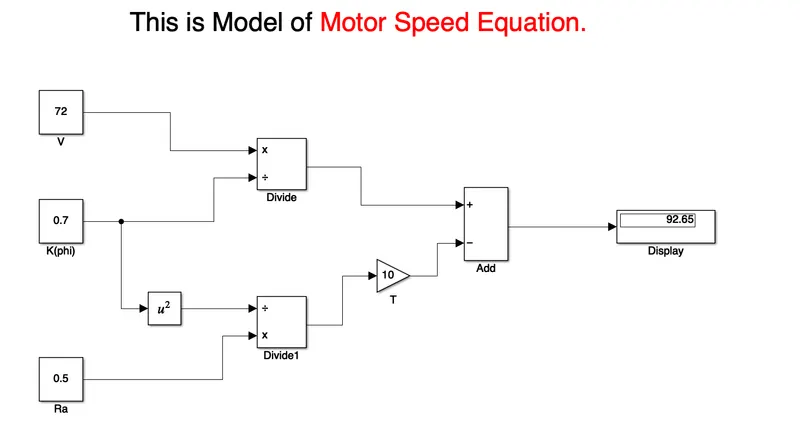
As you can see the answer for this value of the equation is 92.65.
(4) AIM- Read the given Blog and explain about author’s perspective.
Answer- The author's perspective about electric vehicle future technology cannot be predicted easily. The author's point of view is that the induction motor and DC brushless motor both have advantages as well as disadvantages.
- In the case of a DC brushless motor, permanent magnets are used which produces a rotating magnetic field. This magnetic field when induces a current in the conductor. This current results in force generation in the rotor and this results in rotation of the rotor.
- Whereas in the case of induction motor, the current is supplied to the stator which results in the generation of emf, when this emf comes in contact with the rotor which is generally squirrel cage type, this results in current induced in the rotor.
- One of the main differences is that much less rotor heat is generated with the DC brushless drive. Rotor cooling is easier and peak point efficiency is generally higher for this drive. It is mentioned that the DC brushless can drive at the unit power factor, whereas the best power factor for the induction drive is about 85%.
- The construction of a DC brushless motor is costly compared with an induction motor, due to the use of permanent magnets.
- However, in induction motor the speed variation depends upon the frequency input, it is difficult to control.
He also summarises that both induction motor and DC motor have to be developed side by side for EV applications since each has got its advantages and disadvantages.