Week -2
(1) AIM- Make a Model of the Doorbell using a solenoid.
Objective- To build a model of a Doorbell using a solenoid where the switch is closed for 2 secs with the interval gaps.
Given Figure- For doorbell using a solenoid.
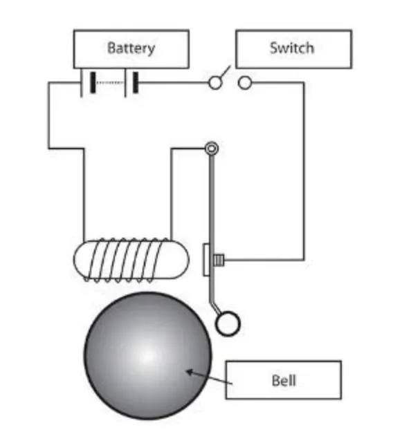
It mainly contains a source for a power supply i.e. Battery, device to ON/OFF the circuit i.e. Switch, device to produce a sound i.e. combination of plunger and bell, and a mechanism for the movement of the plunger i.e. Solenoid that attracts the plunger when current is passed through it and Electromagnetic field is induced around it.
Simulink Model-
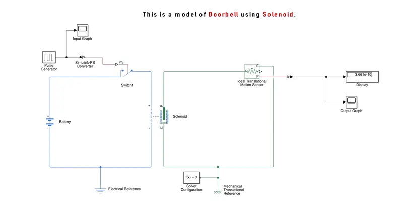
Connections- I had used a "Pulse Generator" as the input source for the circuit, its output port is connected to the PS port of the "Switch" by connecting the "Simulink-PS Converter" in between them for converting the Simulink Signal into Physical Signal. One "Scope" block is also connected to the "Pulse Generator".
Now remaining two electrical ports of the "Switch" are connected to the "Battery" and "Solenoid" electrical terminals as connected in the above image. This loop is also connected with the "Electrical Reference".
After that remaining two mechanical ports of the "Solenoid' i.e. R and C are connected to R and C ports respectively of the "Ideal Translational Motion Sensor". This loop is also connected with the "Mechanical Translational Reference" and "Solver Configuration".
Now in this project, we are using only the P port of the "Ideal Translational Motion Sensor". It is connected to the "Display" and "Scope" for getting the output but before that, it is connected to the "PS-Simulink Converter".
Working- We have to change the parameters of Pulse Generator as given Switch is closed for 2 secs and then released. So phase delay will be 2 secs, pulse width=50%, so period=4 secs(2secs-OFF and 2secs-ON). The stop time for the simulation is 10 secs. Here the square wave will be generated as below-
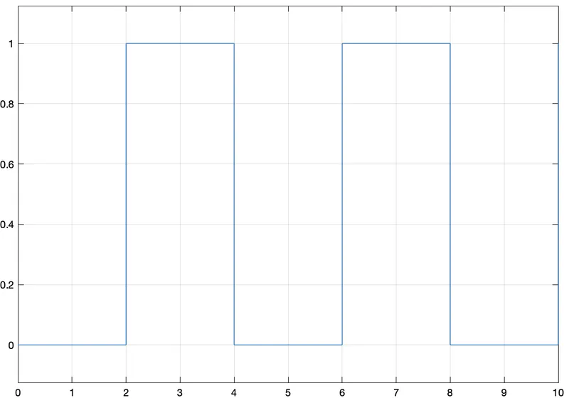
This square wave signal is converted into a Physical signal and applied to the switch. Now when the value of this physical signal is greater than the threshold value set in the switch block, the switch will be closed otherwise it will be open.
When a switch is the closed battery will pass the current to the solenoid and it generates a magnetic field, which will attract the plunger. Ideal translational Motion Sensor is connected to track the motion of plunger in connected display as well as scope.
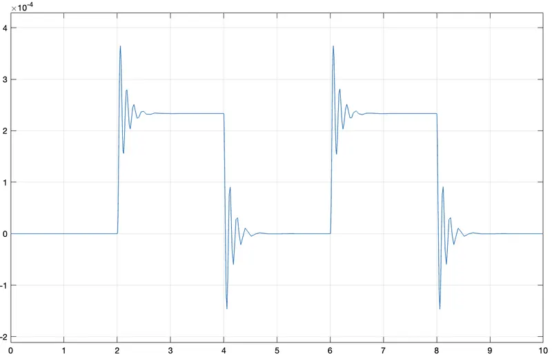
As we can see in the above graph the oscillation and damping are more, so to reduce that we can change the Damping parameter(Change value to 5) of the solenoid and the generated graph will be like this,
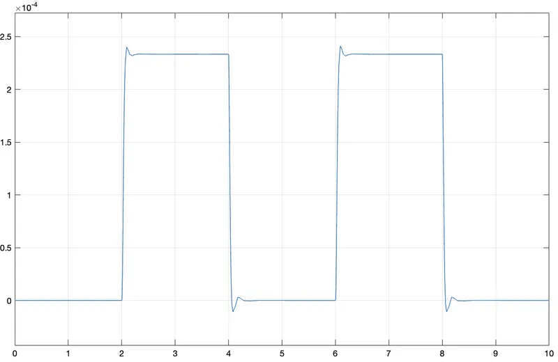
This is how the Doorbell Mechanism works using Solenoid.
(2) AIM- Make a model to sense the temperature using Thermistor and turn ON/OFF the fan as per conditions given.
Objective- Fan will be ON above 25 degree celsius, below that it remains OFF. Temperature range for time period is given:- 20 deg.Cel for 0 to 10 sec, 27 deg.Cel for 10 to 30 sec, 23 deg.Cel for 30 to 50 sec.
Simulink Model-
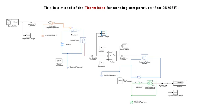
Connections- To provide different temperature as a waveform we use "Signal Builder". Now to maintain temperature difference we use "Controlled Temperature Source". Outport of "Signal Builder" is given to "Controlled Temperature Source" by converting it into Physical Signal. "Scope" is also connected to it for viewing Temperature change graph. Physical Signal of temperature is given to "Thermistor". It is required to connect one "Thermal Reference" with the thermal loop.
Now "Thermistor" electrical ports is connected with the "Battery" to provide power. One current sensor is connected in between them for viewing the current changes in "Scope" block connected with it via "PS-Simulink Converter" block. One "Electrical Reference" and "Solver Configuration" is also required to connect with the loop.
Current flowing in the loop is applied as an input to the "Switch" by converting it into Simulink Signal with the help of "PS-Simulink Converter". Two "Constant" block with value 1 and 0 is connected to "Switch" as shown in above image. One "Scope" is attached with it to view the "Switch" ON/OFF parameter w.r.t.
Output of the "Switch" is connected to "Controlled Voltage Source" via "Simulink-PS Converter"."DC Motor" is now connected with this "Controlled Voltage Source" and One "Electrical Reference" and "Solver Configuration" is also attached with this loop.
Now for detecting motion of fan or motor it is required to attached "Ideal Rotational Motion Sensor" with remaining or Mechanical Ports of "DC Motor" in proper way as done in above image. Also one "Mechanical Rotational Reference" is connected with this loop. One "Display" as well as "Scope" is connected to Output port W of "Ideal Rotational Motion Sensor" as W represents Angular Velocity.
Working- As per given temperature w.r.t. we have to create a signal in signal builder by converting temperature in Kelvin. The Signal will be like this:-
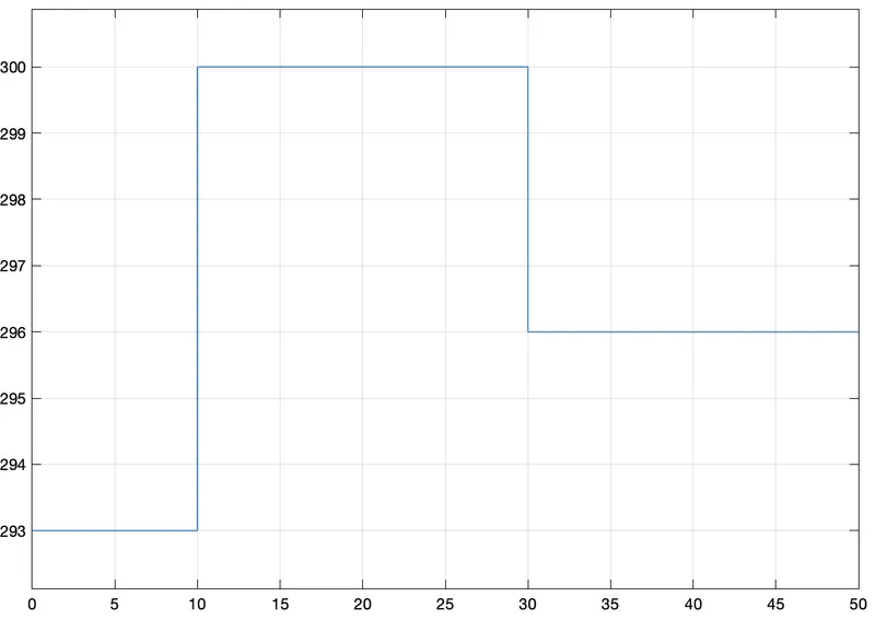
This signal is given to controlled temperature source and finally to thermistor after converting it into Physical signal. Battery will give power to thermistor and as NTC thermistor is used its resistance decreases as temperature increases. So current will change as resistance value changes.
Current sensor will detect the current and gives to PS-Simulink Converter. Scope is used to view the current changes. The graph of current w.r.time (I/t) is as under:-
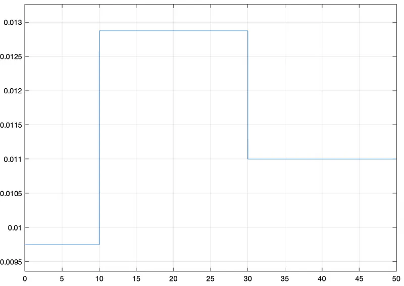
It is also given to switch where some parameter(Threshold) we have to set as per given condition i.e. Switch will closed when current will go beyond 0.012(we have to measure it in current sensor first by applying signal of 25 deg.Cel in signal builder) otherwise it remains open. Now when is closed power will be ON to view this we have to connect scope with switch output port.
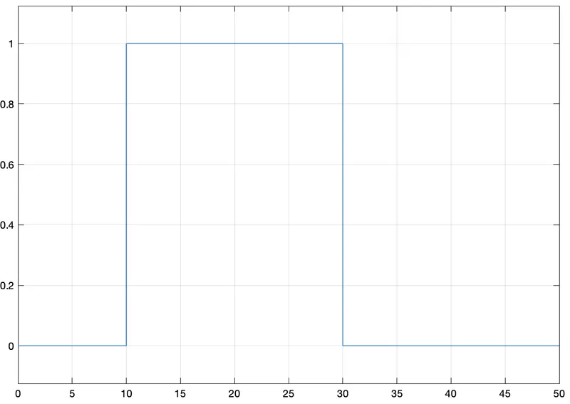
Output of switch is connected to Controlled voltage source which maintains voltage and this is applied to DC Motor. Solver Configuration and Electrical Reference helps to solve circuit and gives output. Fan connected to Dc Motor starts rotating but to confirm that we have to connect Ideal Rotational Motion Sensor to DC Motor. Output port of sensor is connected to display as well as scope to view the graph. The final output graph of Angular Velocity w.r.time is as under:-
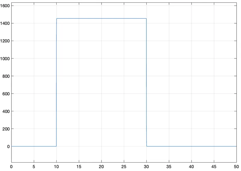
From this we can say that as temperature goes above 25 deg.Cel than Fan will turn ON otherwise remains OFF.