Week-7 Challenge: DC Motor Control
AIM:
To
1. A. Explain a MATLAB demo model named ‘Speed control of a DC motor using BJT H-bridge’.
B. Comment on the armature current shoot-up from the scope results.
C. Refer to the help section of ‘The Four-Quadrant Chopper DC Drive (DC7) block’. Compare it with the H-bridge model.
2. Develop a 2-quadrant chopper using simulink & explain the working of the same with the relevant results. (Refer to article - Multiquadrant operation of motor )
3. Explain in a brief about operation of BLDC motor.
BODY OF CONTENT:
1. A.) ‘Speed control of a DC motor using BJT H-bridge’ MATLAB demo model simulation:
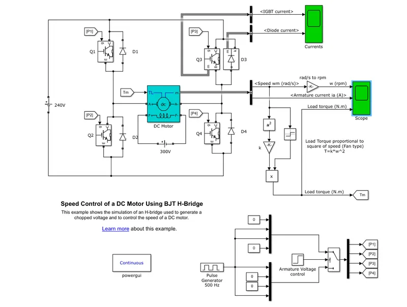
The Bipolar Junction Transistor (BJT) when used for power switching applications, operates as an IGBT. When it is conducting (BJT operating in the saturated region), a forward voltage Vf is developed between collector and emitter (in the range of 1 V). Therefore, the IGBT block can be used to model the BJT device.
The IGBT block does not simulate the gate current controlling the BJT or IGBT. The switch is controlled by a Simulink® signal (1/0). The DC motor uses the preset model (5 HP 24V 1750 rpm). It simulates a fan type load (where Load torque is proportional to square of speed). The armature mean voltage can be varied from 0 to 240 V when the duty cycle (specified in the Pulse Generator block) is varied from 0 to 100%.
The H-bridge consists of four BJT/Diode pairs (BJT simulated by IGBT models). Two transistors are switched simultaneously: Q1 and Q4 or Q2 and Q3. When Q1 and Q4 are fired, a positive voltage is applied to the motor and diodes D2-D3 operate as free-wheeling diodes when Q1 and Q4 are switched off. When Q2 and Q3 are fired, a negative voltage is applied to the motor and diodes D1-D4 operate as free-wheeling diodes when Q2 and Q3 are switched off.
Simulation
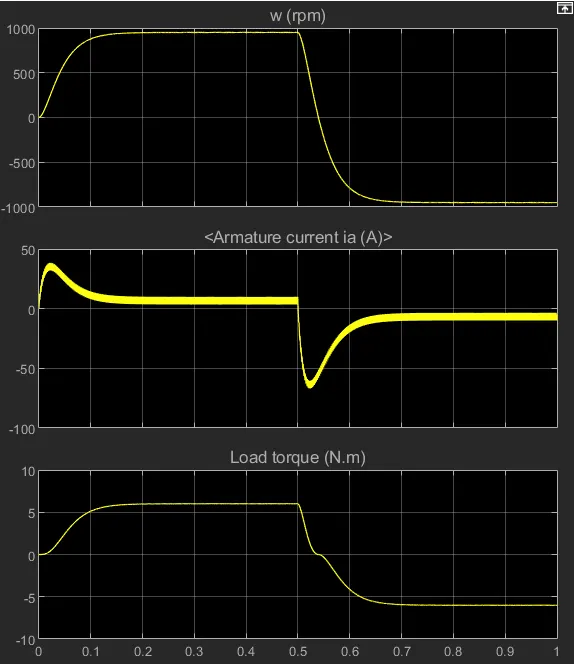
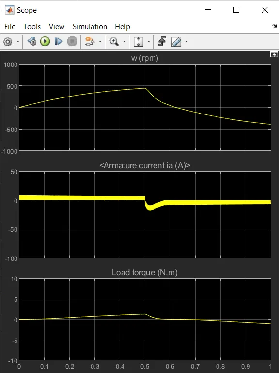
The motor starts in the positive direction with a duty cycle of 75% (mean DC voltage of 180V). At t= 0.5 sec., the armature voltage is suddenly reversed and the motor runs in the negative direction.
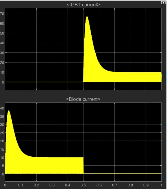
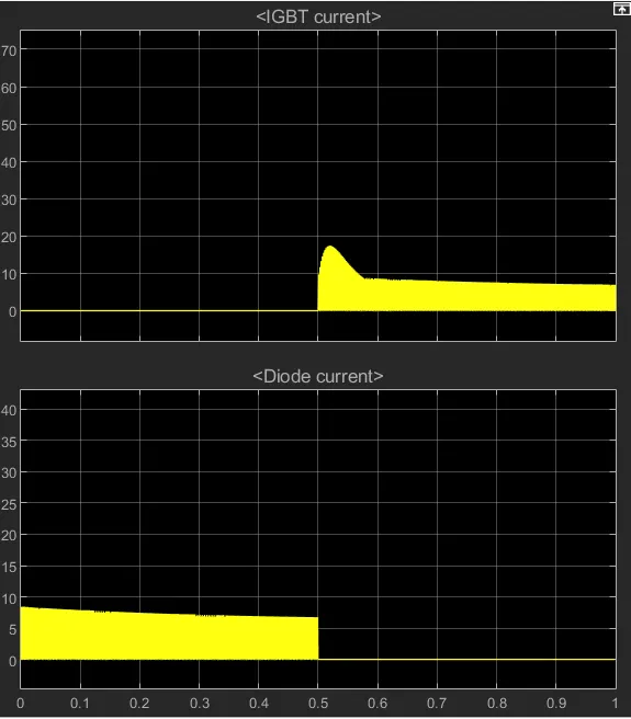
'Scope' shows motor speed, armature current and load torque and 'Currents' shows currents flowing in BJT Q3 and diode D3.
Scope after running results:
Results:
- The cycle reuns for first 75% of duty cycle, which means the cycle runs for the first 75% of the time and is made off for the rest 25% of the time.
- The speed is increased gradually when the load is applied and reaches steady speed at 0.12 seconds. Then, when the load is reversed, the direction of speed is also reversed in the negative direction.
- The torque plot also follows similar pattern to that of speed since both are directly propotional.
- During the first half of the cycle, the diode current passes through the circuit and during the second half of the cycle, the IGBT current passes through the circuit. Here also there is initial shoot up of current while reversing the load.
Armature current shootup: The armature current reaches maximum value during starting of the load applied and reaches constant value for the rest of the cycle till the load is reversed. When the load is reversed, again the armature current shoot up and reaches constant value due to constant speed.
In order to reduce the shoot up value of the armature current when cycle is reversed, the duty cycle is reduced from 75% to 50% in the pulse generator.
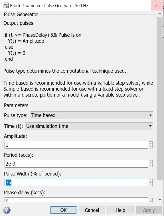
Now the shoot up current value is reduced at the starting of the load reversing.
Scope results of 50% duty cycle:
The Four-Quadrant Chopper DC Drive (DC7) block:
Chopper:
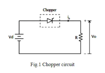
A chopper is a static device which is a DC-DC converter used to obtain variable DC voltage from constant DC voltage. Choppers are of two types. Step-up choppers and Step down choppers. In step up chopper, input voltage is less than output voltage. In step down chopper, input voltage is greater than output voltage.
Type - E Four-Quadrant Chopper DC Drive:
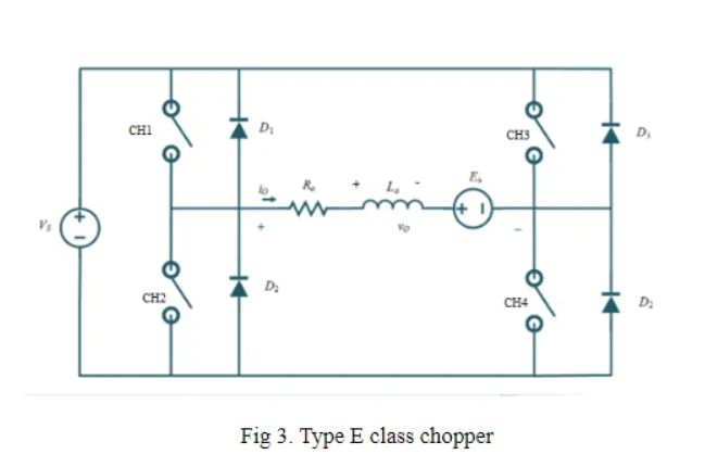
The four-quadrant chopper consisting of 4 semi-conductor switches and 4 diodes arranged in anti-parallel. The 4 choppers are numbered according to which quadrant they belong. Their operation will be in each quadrant and the corresponding chopper only is active in its quadrant.
Chopper circuit diagram:
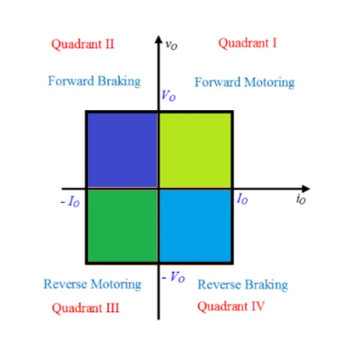
Four quadrant operation of DC motor:
Four quadrant chopper operation:
First quadrant operation:
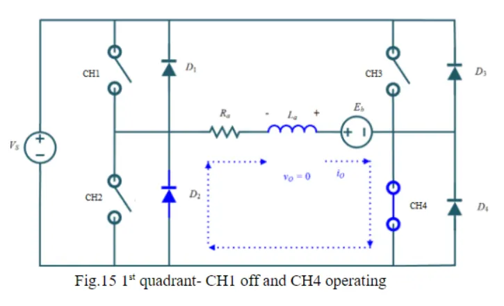
From the chopper circuit diagram, when the CH1 and CH4 is kept ON and CH2, CH3 is kept OFF, the load gets directly connected to the source and the output voltage is equal source voltage.
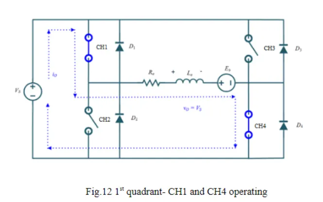
When the CH1 is switched OFF, the load current freewheels the CH4 and D2. During this period, both load current and load voltage remain positive. Hence it operates in the 1st quadrant.
Second quadrant operation:
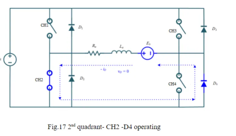
During second quadrant operation, the CH2 is switched ON and the CH2,CH3,CH4 are made to switch OFF. DC source in the load drives the current through the D4 and CH2.
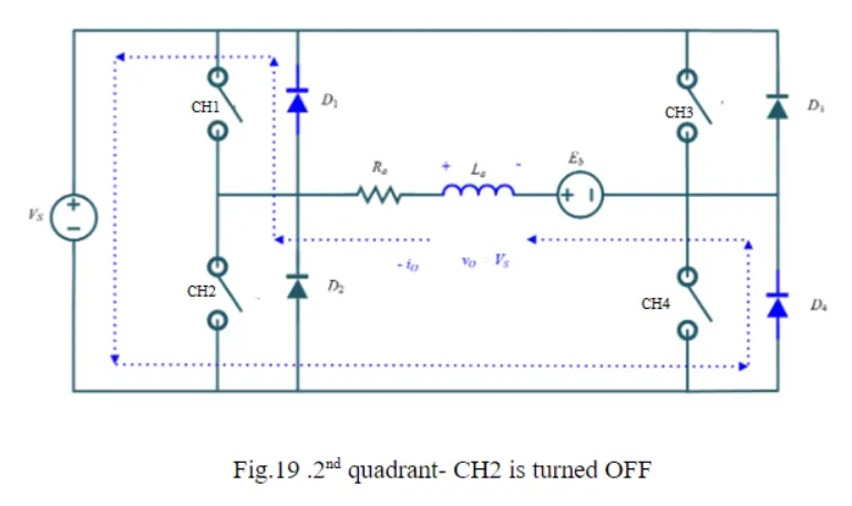
When CH2 is made off, current is fed back to the source through D1 and D4. As the load voltage is positive and the current Io is negative, it is operated in the 2nd quadrant.
Third quadrant operation:
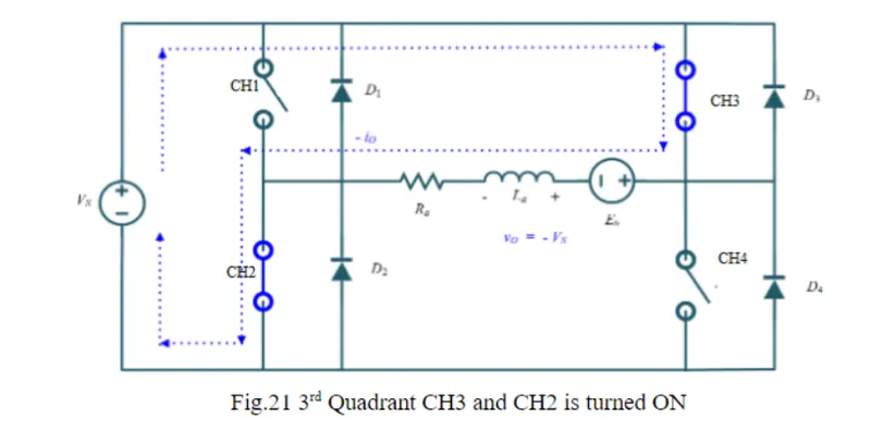
For third quadrant operation, thyristor CH1 is kept off, CH2 is kept on and CH3 is operated, polarity of armature back emf Eb must be reversed for this quadrant operation. With thyristor CH3 is on, armature gets connected to source V so that both Va , Ia are negative, leading to third quadrant operation. When CH3 is turned off,negative current freewheels through CH2,D2. In this manner only Va and Ia can be controlled in the third quadrant.
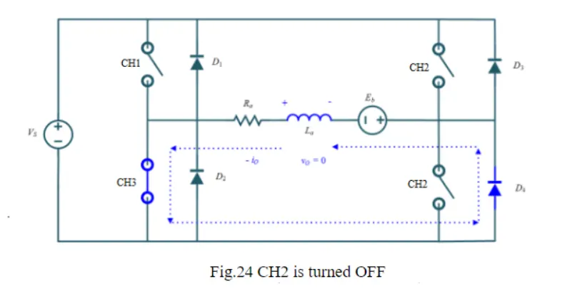
Fourth quadrant operation:
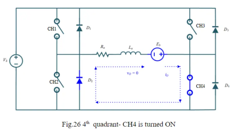
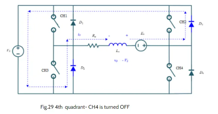
Here thyristor CH4 is operated and other devices kept off, back emf Eb must have its polarity reversed as in third quadrant operation. With CH4 on, positive current flows through CH4,D2,La and Eb (armature). Armature inductance La stores energy during the time CH4 is on. When CH4 is turned off, current is fed back to source through diodes D2, D3.Here armature voltage Va is negative, but Ia is positive, leading to the chopper drive operation in the fourth quadrant. Also power is fed back from armature to source.
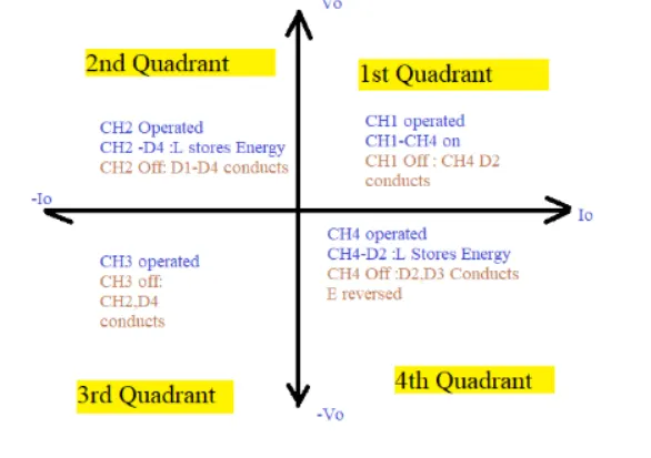
The operation of 4 quadtant chopper is summarized as below.
The Four-Quadrant Chopper DC Drive (DC7) block model simulation:
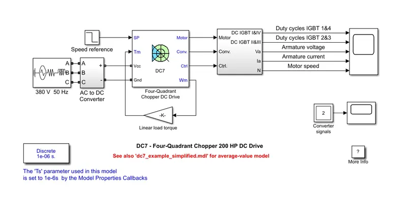
The 200 HP DC motor is separately excited with a constant 150 V DC field voltage source. The armature voltage is provided by an IGBT converter controlled by two PI regulators. The converter is fed by a 515 V DC bus obtained by rectification of a 380 V AC 50 Hz voltage source. In order to limit the DC bus voltage during dynamic braking mode, a braking chopper has been added between the diode rectifier and the DC7 block.
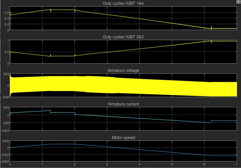
The first regulator is a speed regulator, followed by a current regulator. The speed regulator outputs the armature current reference (in p.u.) used by the current controller in order to obtain the electromagnetic torque needed to reach the desired speed. The speed reference change rate follows acceleration and deceleration ramps in order to avoid sudden reference changes that could cause armature over-current and destabilize the system. The current regulator controls the armature current by computing the appropriate duty ratios of the 5 kHz pulses of the four IGBT devices (Pulse Width Modulation). For proper system behaviour, the instantaneous pulse values of IGBT devices 1 and 4 are opposite to those of IGBT devices 2 and 3. This generates the average armature voltage needed to obtain the desired armature current. In order to limit the amplitude of the current oscillations, a smoothing inductance is placed in series with the armature circuit.
Results:
Comparision of Four-Quadrant Chopper DC Drive (DC7) block to H-bridge model:
- The Four-quadrant chopper DC drive can be operated in all the four quadrants such as
Forward motoring (1st quadrant)
Forward braking (2nd quadrant)
Reverse motoring (3rd quadrant)
Reverse braking (4th quadrant)
whereas, in H-bridge model, it operates in two modes only.
Forward motoring
Reverse motoring - In Four-quadrant regenerative braking in both forward and reverse direction is possible, whereas in H-bridge model only forward motoring is possible and regenerative braking is not possible.
- H-bridge model is used in Robotics applications whereas in Four-quadrant DC chopper model is used in trolley cars, battery operated vehicles, traction motor controls and other commercial and industrial applications.
- BJT H- bridge model is a closed loop model that takes feedback from the system whereas in four-quadrand chopper, it is open loop.
- PI controller is used for controlling pulse width in BJT H-bridge model whereas in it is not in case of 4-quadrant chopper since it is open loop.
- In H-bridge, the polarity of the voltage applied to the load is reversed but in 4 quadrant chopper, the electroniic switch is used to interrupt the signal.
- 4 quadrant model have high switching frequency whereas H- bridge model have low switching frequency.
2-quadrant chopper using simulink & it's working:
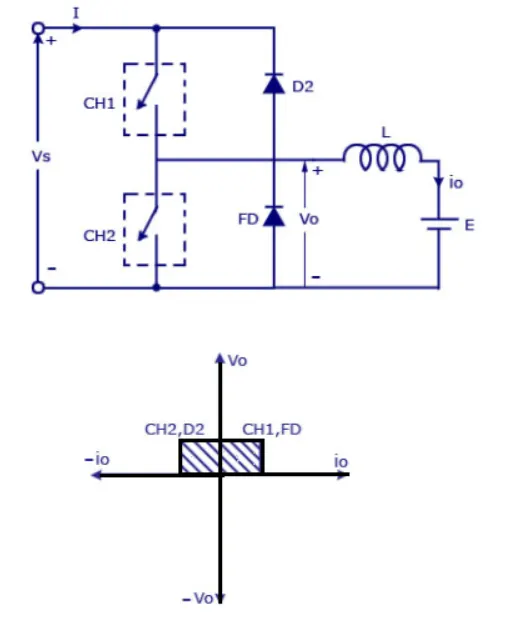
2-quadrant chopper:
Working:
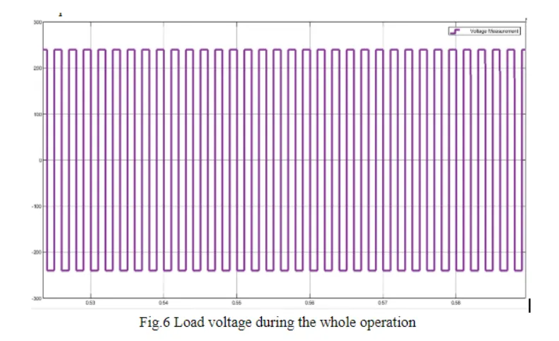
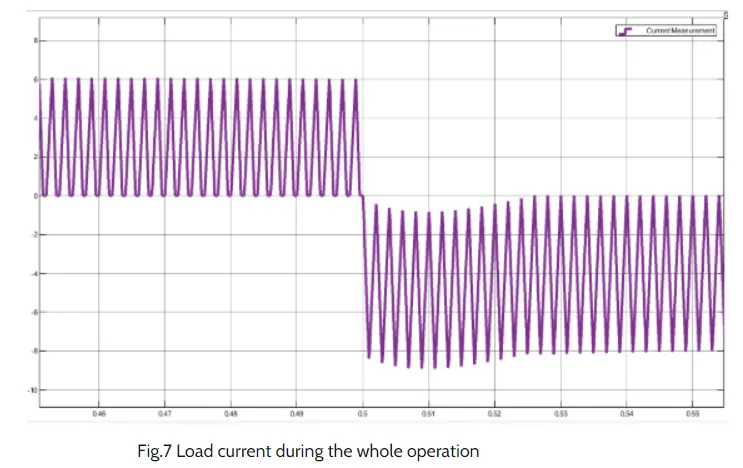
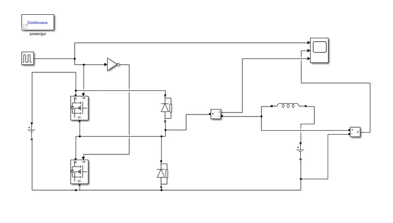
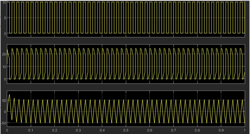
In this average voltage will always be positive and the average load current wil be positive or negative. When the chopper CH1 is ON, the current flows from source to load. The inductor stores energy. When CH1 is off, the freewheeling diode starts conducting the output voltage Vo will be equal to Vs. The direction of load current Io will be reversed. The current Io will be flowing towards the source. The load current will be negative when CH2 is on. The current completes its path through diode d2.
Simulink model:
Results:
BLDC motor:
A brushless DC electric motor, is a synchronous motor using a direct current (DC) power supply. It uses an electronic closed loop controller to switch DC currents to the motor windings producing magnetic fields which effectively rotate in space and which the permanent magnet rotor follows. The controller adjusts the phase and amplitude of the DC current pulses to control the speed and torque of the motor. This control system is an alternative to the mechanical commutator (brushes) used in many conventional electric motors.
Construction:
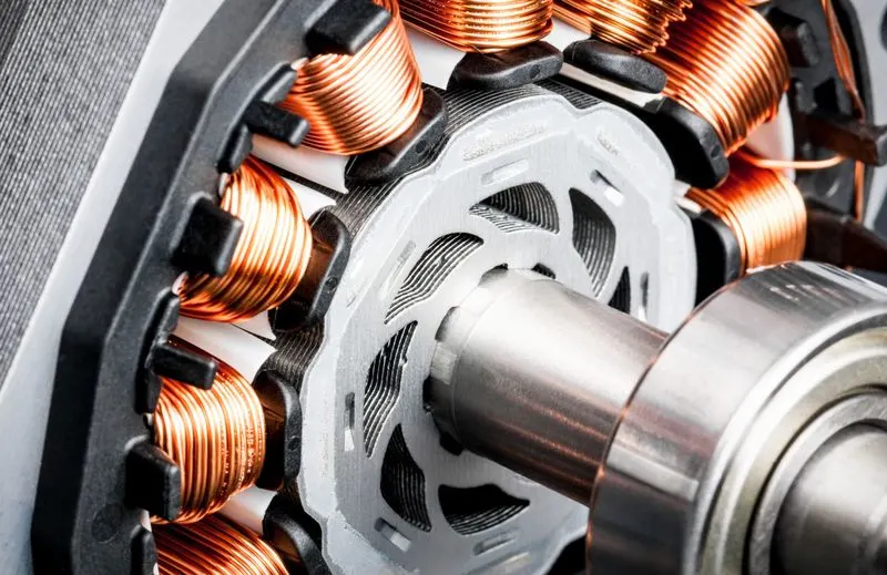
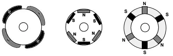
Here, the rotor is a permanent magnet; the coils do not rotate, but are instead fixed in place on the stator. Because the coils do not move, there is no need for brushes and a commutator. A BLDC motor with three coils on the stator will have six electrical wires (two to each coil) extending from these coils. In most implementations three of these wires will be connected internally, with the three remaining wires extending from the motor body (in contrast to the two wires extending from the brushed motor described earlier). Wiring in the BLDC motor case is more complicated than simply connecting the power cell’s positive and negative terminals; we will look more closely at how these motors work in the second session of this series.
Working principle:
BLDC motor works on the principle similar to that of a Brushed DC motor. The Lorentz force law which states that whenever a current carrying conductor placed in a magnetic field it experiences a force. As a consequence of reaction force, the magnet will experience an equal and opposite force. In the BLDC motor, the current carrying conductor is stationary and the permanent magnet is moving.
Working:
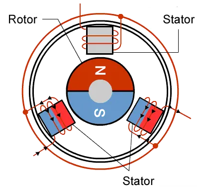
With a BLDC motor, it is the permanent magnet that rotates; rotation is achieved by changing the direction of the magnetic fields generated by the surrounding stationary coils. To control the rotation, the magnitude and direction of the current into these coils are adjusted.
Control of BLDC motor:
In every industry there are processes some form that require adjustment for normal operation. Such adjustments are usually accomplished with variable speed drive and it consists of
☞Controller
☞Power Converter
☞Electric Motor
- Controller: The controller generates PWM signal to the converter & hence forms the heart of the Variable speed system.
- Power Converter: It controls the power flow from an AC supply to the motor by appropriate control of power semiconductor switches (part of power Converter)
- Electric Motor: It is connected directly/indirectly to the load
BLDC motor operation:
A permanent Magnet AC motor, which has a trapezoidal back emf, is referred to as brushless DC motor (BLDC). The BLDC drive system is based on the feedback of rotor system at fixed points for commutation of the phase currents.
The BLDC motor requires quasi-rectangle shaped currents fed into the machine. Alternatively, the voltage may be applied to the motor every 120°, with current limit to hold the current within motor capabilities. Because the phase currents are excited in synchronism with the constant part of the back emf, constant torque is generated. The electromagnetic torque of the BLDC motor is related to the product of phase, back emf and current. The back emf in each phase are trapezoidal in shape and are displaced by 120 electrical degree with respect to each other in 3 phase machine. A rectangle current pulse is injected into each phase so that current coincides with the ack emf waveform; hence the motor develops an almost constant toque.
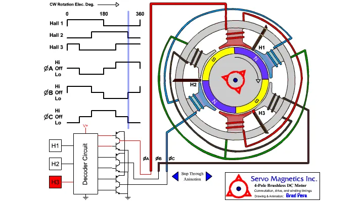
BLDC Hall sensor:
Hall Effect sensor provides the portion of information needed to synchronize the motor excitation with rotor position in order to produce constant torque. It detects the change in magnetic field. The rotor magnets are used as triggers to the Hall Sensor. A signal conditioning circuit integrated within the Hall switch provides a TTL-compatible pulse with sharp edges. Three Hall Sensors placed 120° apart, are mounted on the stator frame. The Hall Sensor digital signals are used to sense the rotor.
Advantages:
- It can operate at speeds above 10,000 rpm in both loaded and unloaded conditions.
- BLDC motors have the highest running torque per cubic inch of any DC motor.
- BLDC motors do not have brushes, meaning they are more reliable and have life expectancies of over 10,000 hours. This results in fewer instances of replacement or repair and less overall down time.
- Inner rotor Brushless DC motors have low rotor inertia, allowing them to accelerate, decelerate, and reverse direction quickly.
CONCLUSION:
- The MATLAB demo model named ‘Speed control of a DC motor using BJT H-bridge’ is explained in detail and results are commented.
- 2-quadrant chopper using simulink is developed and its working is explained.
- 'The Four-Quadrant Chopper DC Drive (DC7) block’ working is expalined and compared with the BJT H-bridge model.
- The operation of BLDC motor is explained in detail.
References:
https://www.renesas.com/us/en/support/engineer-school/brushless-dc-motor-01-overview