Week-7 Challenge: DC Motor Control
1.A
Aim: - To Study the model ”Speed control of a DC motor using BJT H-bridge” in MATLAB.
Description: -
IGBT--> IGBT stands for Insulated Gate Bipolar Transistor. It is unipolar and unidirectional fully controlled switch. It is a voltage controlled device. IGBT has 3 terminals G is the gate input which allows us to control the ON and OFF of IGBT, E – Emitter and C- is the collector terminal.
The model for study
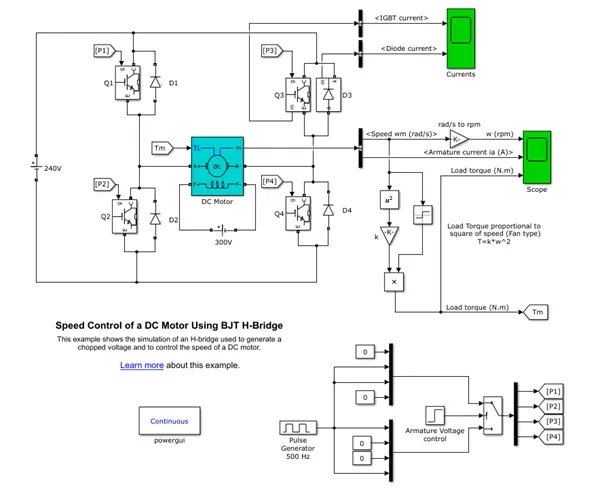
DC Motor --> The DC motor used is separately excited DC motor with a fixed field supply. This DC motor is controlled by the H-bridge model.
H- Bridge --> The H –bridge model is created by connect 4 switches in this case IGBT at 4 legs of a H.
IGBT --> The IGBTs are connected in parallel with the diodes to provide freewheeling path.
Operation of the Pulse generating circuit à 4 oscillating pulses are created. P1 an P4 operates for 0.5 sec and P2 and P3 operates for 0.5 sec. The pulses are shown below
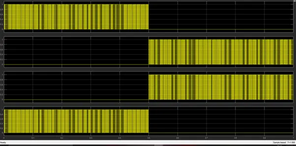
Operation of H- Bridge --> For 1st half time period i.e. 0.5 sec Q1 and Q4 are conducting. Again for the 2nd half i.e. 0.5 sec Q2 and Q3 are operating.
Result: -
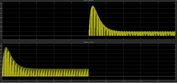
The IGBT and the diode current are
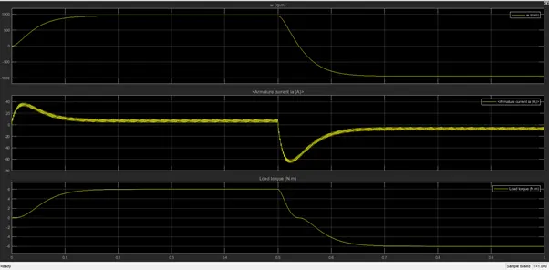
The output of the motor is show in the fig below for 2 different duty cycles.
With 75% duty cycle
With 50% duty cycle
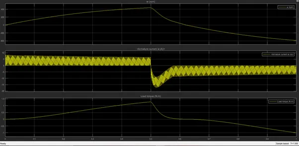
- With the 75% duty cycle the speed and the torques reaches the constant region but with 50% duty cycle they cannot reach the constant region before the current gets reversed.
B.
The shoot up in the armature current occurs due to switching in the circuit causing heat losses. To prevent the excessive heating a heat sink is used.
C.
The 4 quadrant chopper DC drive (DC7) has a H bridge configuration.
- A smoothing inductance is used to smooth out the ripples.
- The control signal to the IGBTs are controlled by a PI controller.
|
4 quadrant chopper DC drive (DC7) |
H bridge |
|
All 4 quadrant operation i.e. forward motoring, forward braking, reverse motoring and reverse braking are possible. |
Only motoring and braking mode are possible. |
|
Control is complex process |
Control are comparatively easier |
|
More efficient |
Comparatively less efficient |
2.
The 2 quadrant chopper operation is shown below: -
When Q1 is ON the current flows form Vs to load and the current is positive. When Q1 is OFF the freewheeling diode D1 starts conducting. When the current is negative i.e. the motor starts delivering power (Regenerative Braking) Q2 is conducting. When Q2 stops it freewheels through D2.
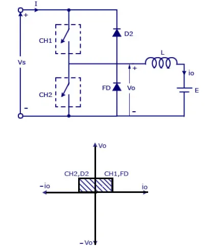
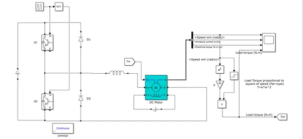
The model prepared for the 2 quadrant chopper application is shown below: -
The motor output is shown below: -
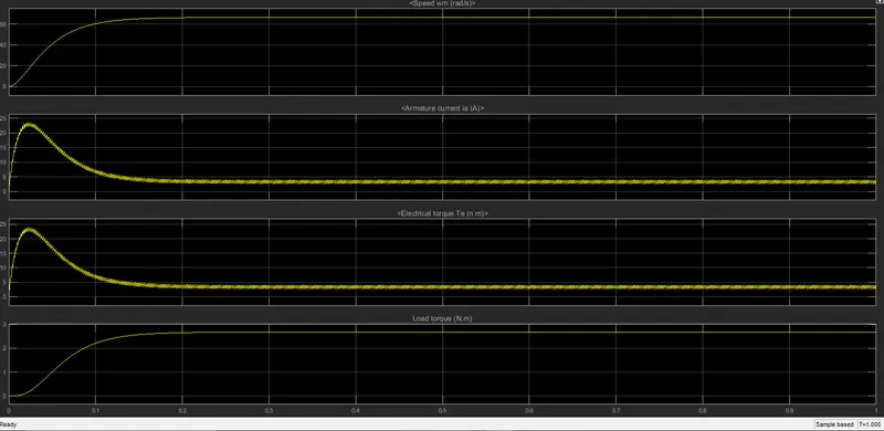
Only 2 modes are possible with this kind of chopper viz, motoring mode and braking mode
Hence this chopper is used for motoring and regenerative braking operation of the motor.
3.
Brushless DC motor:
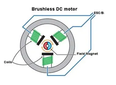
The brushless dc motor has a permanent magnet rotor which has its own magnetic field. The stator contains the coils arranged in three phases. We will apply DC power to the coils hence creating a magnetic field. The interaction between these 2 magnetic field causes to rotor to rotate.
Suppose the poles of the rotor are fixed, we will energise the coils which are closer to the poles in such a way that the force of attraction causes the rotor to rotate. Suppose the coli A and Coli B are on both side of the rotor pole the current in coil A should be such that it attracts the rotor and current in coil B should be such that it repel the rotor. Overall the Rotor gets rotated. This requires a complex control mechanism. This is controlled by Hall sensor. One of the most commonly used control techniques for BLDC motor is pulse width modulation (PWM) and hysteresis current control associated with continuous control theory
This motor is also known as Permanent magnet brushless DC motor.
The supply is given like this
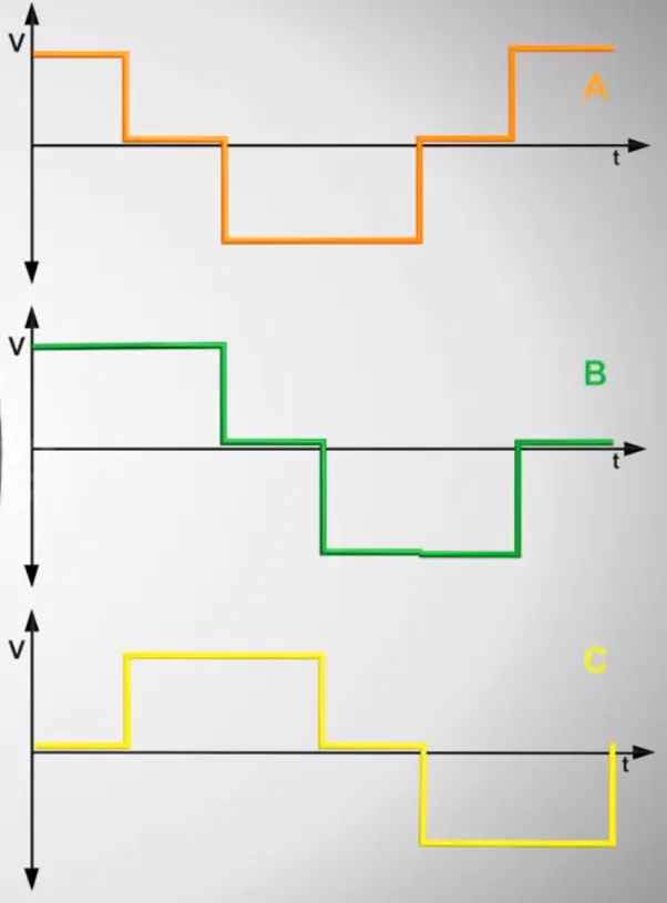
This motor gives a very desirable constant torque characteristics.