Project
Aim: - To prepare a technical report of system level inspection of 5 models of BAJA All Terrain Vehicle (ATV) model.
Models: -
- i.cvtModel ii. cvtModel_dashboard iii.cvtModel_data
- cvtModel_cvtratio_rpm
- cvtModel_dashboard_mapped
- cvtModel_mapped
Theory: -
All the models mentioned above has a number of similar blocks. The only difference in the different model is the input to the CVT block, Throttle and Brake.
Before we dive deep into the Simulink model some important terms needed to be described as follows:
CVT: - It stand for Continuously Variable Transmission. It is an automatic transmission which continuously varies the gear ratio to maintain a constant speed of the engine. Thus it allows the vehicle to move in different speed while keeping a fixed rpm at the engine. Mostly it uses a v-belt.
ATV: It stands for All Terrain Vehicle. It is vehicle designed to run at the rough terrain.
SAE: It stands for Society of Automotive Engineers. BAJA SAE is a competition for the college run by the Society of Automotive Engineers. It aims to build and designs ATVs.
Simulink Model
The model has mainly 4 sections: -
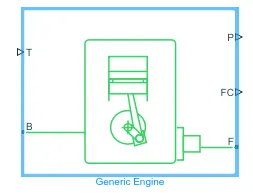
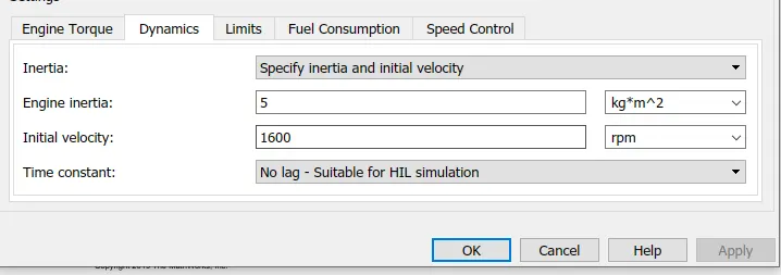
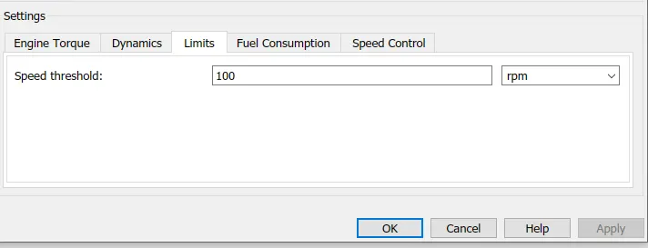
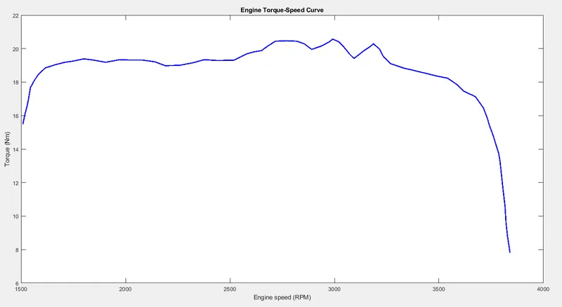
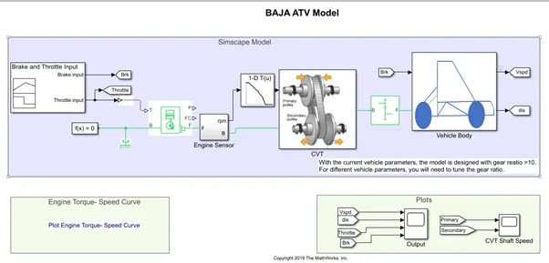
Generic Engine is used as the engine of the vehicle. T is the throttle input and B and F are the mechanical reserving ports. P and FC ports are the power and fuel consumption port which remains unconnected. The B port is connected to a Mechanical Rotational Reference and the F port is connected to the variable gear ratio and also it is fed to the engine sensor block.
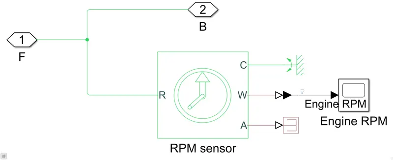
Engine Sensor: - It is a subsystem which consists of Ideal Mechanical Rotational Sensor. W and A port gives velocity and angle of the input signal through R relative to port C. The output of the generic engine is fed into the R port of the sensor and the C port is connected to a mechanical reference. Since it is simscape block we use a physical signal to Simulink converter and a scope to see the output. Here we are not interested in the angle so the A port is terminated using a Physical signal terminator.
CVT subsystem: -
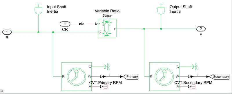
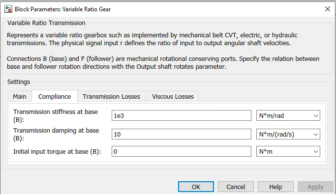
An inertia block is connected to the output of the generic engine and we measure the speed here which is the engine speed using an ideal mechanical rotational sensor (as mentioned above). The output of the generic engine with an inertia attached id fed into an Ideal Variable Transmission. The port r defines the ratio of the input to output angular shaft velocities. The B and F are the base and follower mechanical rotational conserving ports. The output of the Variable Transmission is connected to a inertia and is fed to a Gear Box. The out velocity is also measured using the Mechanical rotational sensor as mentioned above.
Gear Box: - It is a simple gear box which increases or decreases the velocity according to the gear ratio.
`r_B w_B =w_F r_F`
Vehicle Body subsystem: -
Vehicle body:-
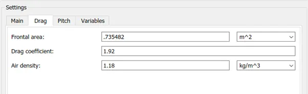
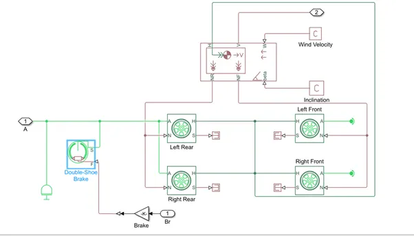
- This makes the body of the vehicle. A vehicle body block is used that accounts for only horizontal forces.
- NR and NF are for the forces acting on the rear wheel and front wheel respectively.
- It does not account for any vertical motion.
- The Beta port accounts for the road inclination and the W port is for the wind velocity.
- H is the mechanical conserving port and the V is the vehicle velocity.
We modelled the vehicle body with 4 titres 2 in front and 2 in back.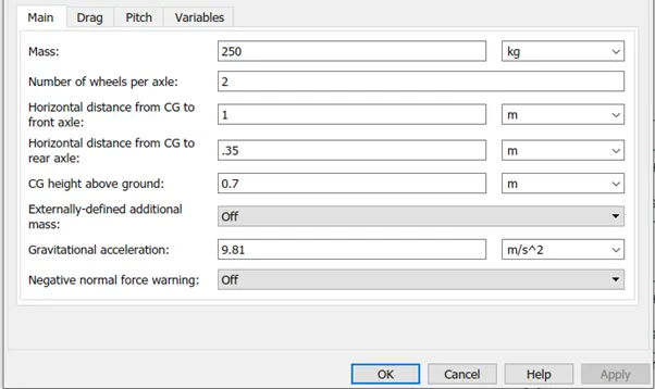
Tire: -
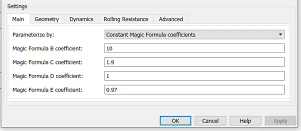
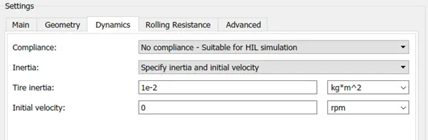
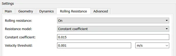
- For tire we used tire (Magic Formula) block. The N port is the physical signal port for the force acting on the tire.
- This N port of the 2 front tire is connected with the NF and the 2 back tires are connected with the NR. A port is the mechanical rotational conserving port for the wheel axle.
- We connect a brake signal in both the rear wheels and for the front wheel we connect a rotational reference.
- S port is for the tire slip. Since we are not interested in the slip we connect a physical signal terminator.
- H port is the physical signal conserving port and h port of all the tires are connected to the H of the Vehicle body.


Brake: -
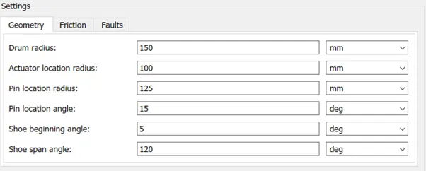
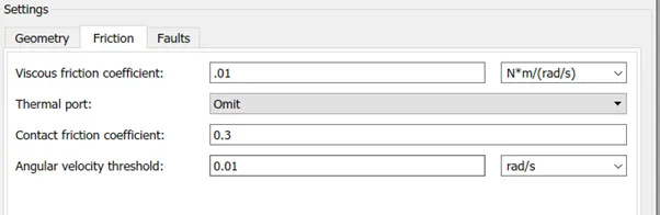
- For the Brake signal the input is multiplied with a gain of 1000 and fed into the double shoe brake.
- The F port is the physical signal force input and S is the mechanical conservation port connected to the shaft.
- cvtModel
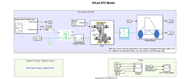
Here, the input Throttle, Brake and the CVT ratio are given by a signal builder block.
Throttle input and Brake input: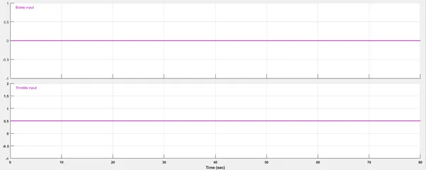
Throttle input is set to 0.5 and brake is 0 for the entire transmission.
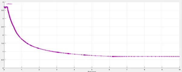
CVT ratio:
- iii. cvtModel_data
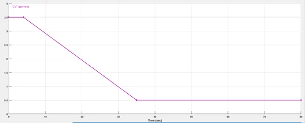
This model is exactly same as the 1 model with the change signal of CVT ratio.Here the CVT ratio is decreasing linearly compared to the above model.
- cvtModel_dashboard
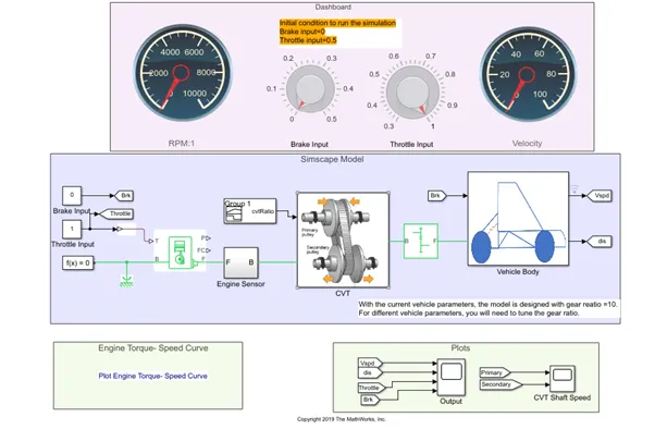
This model has an additional dashboard with which we can vary the brake and throttle inputs. Hence there is no need of signal builder for this signals. The CVT ratio is same and is fed by the signal builder as shown in Fig: 18.
- cvtModel_cvtratio_rpm
The CVT Ratio input is given by a lookup table which is fed by the velocity from the motion sensor.
The CVT ratio varies from 3.5 to 0.5.
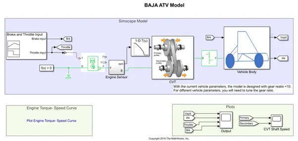
Fig: 21
- cvtModel_dashboard_mapped
In this model the CVT ratio is also fed with the lookup table but the lookup table is fed with the output speed of the engine forming a feedback loop. The gear ratio for the gear box is 12.
Result
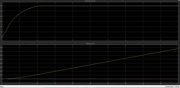
In the result we will be seeing the velocity of the vehicle corresponding to the distance travelled.
For model 1
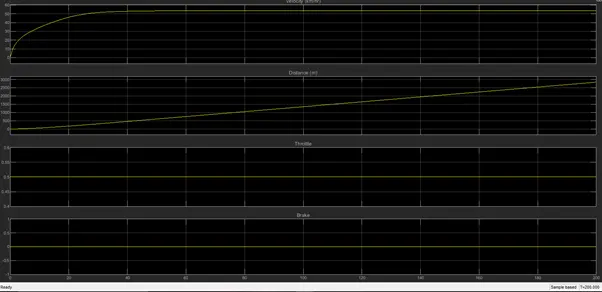
Here we kept the Throttle input constant hence the speed increases gradually and then becomes constant at 53.5317(by logging data into the workspace).
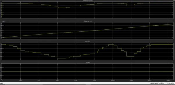
With dashboard model (1.2) we can change the Throttle input and see the corresponding variation in the speed of the vehicle.
For the model 2
The results are almost similar with a little change in the value of the output speed. Here the Throttle input is constant at 1 and hence the speed of the vehicle is little high 60 compared to the previous model.
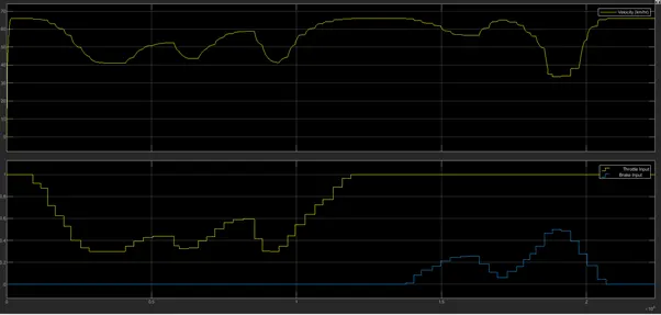
For model 3
We can see the ass the throttle is reduce the vehicle speed also reduces and the with the increase in brake input the vehicle speed reduces. The maximum speed reached by the vehicle is 65.9106.
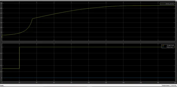
For model 4
Here the acceleration is little slow and it takes more time to to reach the constant speed.The maximum value is 65.9048.
Conclusion:
The system level simulation and study has been prepared for the Baja ATV with and wothout dashboard and with look up tables as well as with feedback loop is studied