Week -2
Study: - 1
Aim: - To make Simulink model of doorbell using solenoid.
Theory: - Solenoid is an electro-mechanical system where an electrical input created a magnetic field in a coil. This magnetic field creates a magnetic force which helps in a mechanical movement.
Simulink Model: -
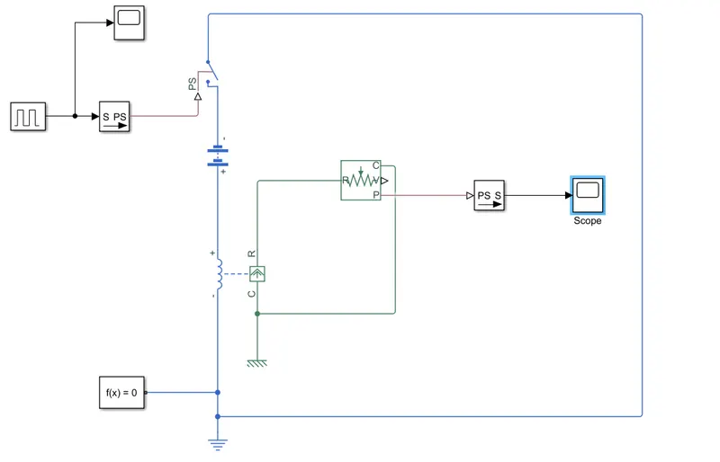
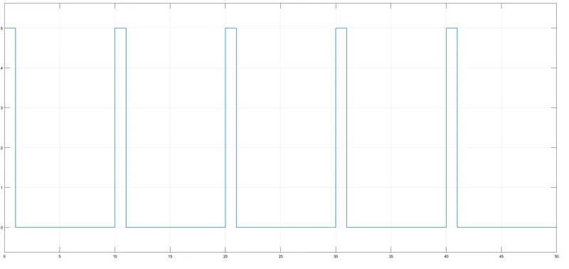
In the above model, we have used following blocks: -
- Pulse Generator-To generate a pulse.
- Battery- To supply electrical power.
- Solenoid- Electromechanical system which takes electrical input and convert it to mechanical power.
- Switch-It disconnects the circuit
- Ideal Translational Motion Sensor- to detect the translational motion of the solenoid.
- Solver Configuration
- PS-Simulink converter-To convert physical signal to simulink signal.
- Simulink-PS converter-To convert simulink signal to physical signal.
- Scope-To display the output graph.
- Electrical Reference-Provides reference for electrical circuit.
- Transitional reference-Provide Translational reference.
Procedure:-
- First, a Pulse generator is connected to a control port of a switch via a simulink to physical signal converter block.
- Second,a battery,electrical part of the solenoid and the electrical part of the above mentioned switch are connected in series and the circuit is completed using a electrical reference.
- Third,for the mechanical part of the circuit,R port of the solenoid is coonected to the r port of the translational motion sensor nad the C port of both solenoid and the translational motion sensor to a translational reference. The P(Position) port of the translational motion sensor is connected to the scope via physical signal to simulink converter.
Result:-
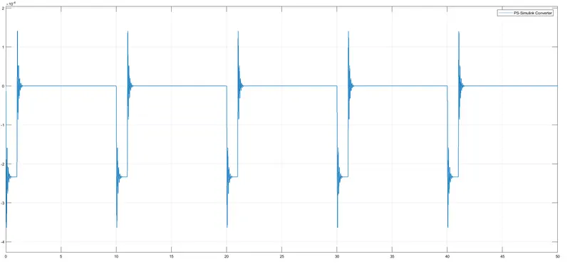
Observation: - We can see the vibration in the output, which can be implemented as a bell.
Study:-2
Aim: - Use a thermistor to sense the temperature of a heater.
Theory: - Thermistor is basically a resistor whose resistance depends on temperature. It is of 2 type: - Negative temperature coefficient and positive temperature coefficient. A negative temperature coefficient thermistor is that whose resistance decreases with increase in temperature. A positive temperature coefficient is that whose resistance increases with increase in temperature.
Simulink Model: -
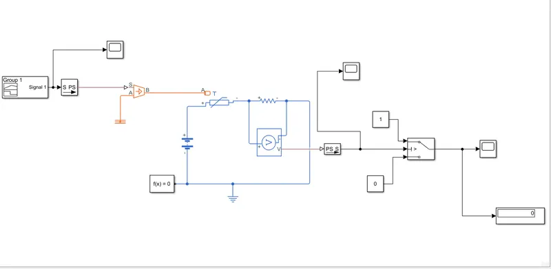
This is the Simulink diagram used for the study.
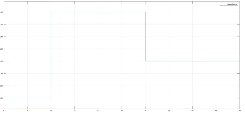
This is the signal fed into the thermal source as per the question (20 °C from 0 to 10 seconds, 27 °C from 10 to 30 seconds, 23 °C from 30 to 50 seconds).Here Degree is converted in to Kelvin using the formula
Tk = Tc +273
Where,
Tk ---- Temperature in Kelvin
Tc ---- Temperature in Celsius
In the above model, we have used following blocks: -
- Thermistor-It is a thermal resistance.
- Signal Builder-To build the mentioned signal
- Controlled Temperature Source- To input the control temperature to the thermistor.
- Resistor-
- Voltage Sensor-To measure the voltage across the resistor.
- Battery-To supply electrical power.
- Switch-It is a controlled switch which allows signal through port 1 if port 2 input is greater than thresold otherwise allows port 3 input.
- Solver Configuration
- Scope-To display the output graph.
- Display-To display the output value of voltage.
- PS-Simulink converter-To convert physical signal to simulink signal.
- Simulink-PS converter-To convert simulink signal to physical signal.
- Constant-Provides a constant value to a block.
- Electrical reference-Provides reference for electrical circuit.
- Thermal Reference-Provide Translational reference.
Procedure:-
- First we fed the controlled thermal source with a Signal builder block with a the mentioned signal via a Simulink to Physical signal converter.
- Then the thermistor is connected in series with a resistor and a battery and the circuit is completed with a electrical reference.
- A voltage source is connected across the resistor to get the value at a particular temperature.
- The output of voltage source is connected to the control port of the 3 potr switch.
- Our aim is to drive a load when the temp is greater than 25 °C. So we measure the voltage at 25 °C which is 0.01189. This is given as a threshold value to the switch.
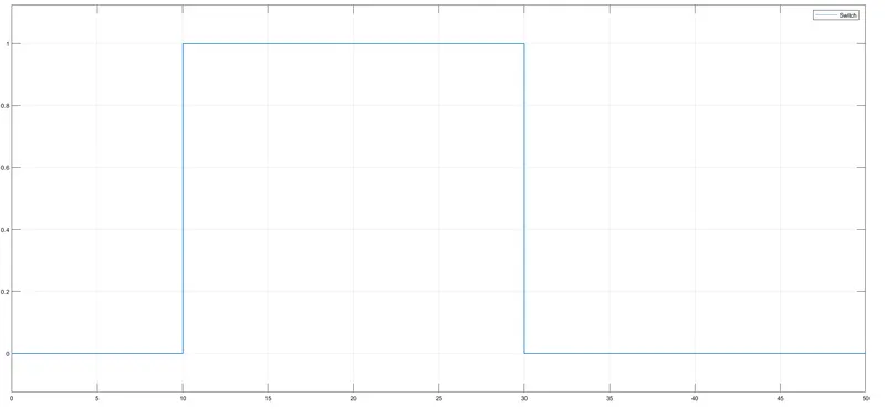
Observation:-
We can see the output is 1 where the temperature is greater than 25 °C i.e. in range 10-30 sec.