Week-7 Challenge: DC Motor Control
Aim: To explain the MATLAB model 'Speed control of a DC motor using BJT H-bridge
Principle/Explanation: The BJT consists of an H-bridge which comprises of 4 BJT/Diode pairs, this BJT in this condition operates as an IGBT. When operated in the saturated region there is the forward voltage developed between collected and emitter called Vf.
Operation: The two transistors are operating simultaneously, i.e. Q1 and Q4 or Q2 and Q3. A positive voltage is applied to the motor and diodes when Q1 and Q4 are in operating conditions. Diodes D2 and D3 operate as free-wheeling diodes when Q1 and Q4 are turned off. D1 and D4 operate as free-wheeling diodes when Q2 and Q3 are switched off and a negative voltage is applied to the motor and diodes when they are in operating conditions.
MATLAB model and results:
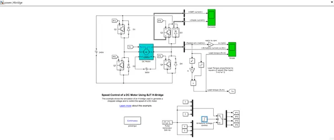
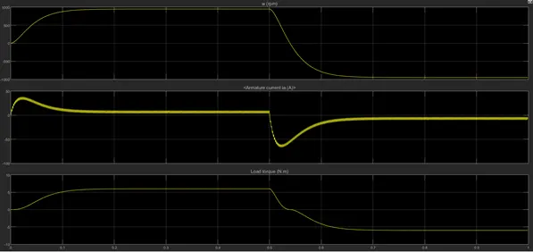
The results are obtained for a duty cycle of 75% at 0.5 seconds. The armature voltage reverses polarity and the motor runs in the opposite direction after a time period of 0.5 seconds. We can notice a small peak in the increase of all parameters after which they all remain constant till 0.5 seconds. After 0.5 seconds, the armature voltage and torque are negative (motor running in the opposite direction)
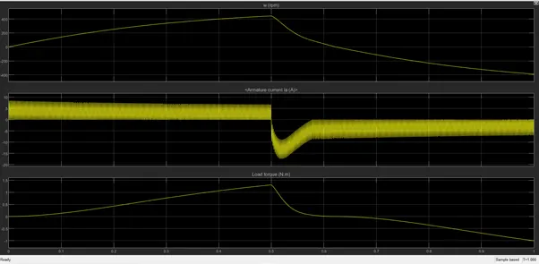
We have also simulated results when the duty cycle is 50% at 0.5 seconds, which is in the plot shown below. There is no armature current shoot when the duty cycle is reduced to 50% as the motor changes from forward to reverse. The transient state has reduced due to this change and there are no current losses too.
- Aim: To discuss ‘The Four-Quadrant Chopper DC drive (DC 7) block and compare it to the H-bridge model
Principle/circuit diagram:
Chopper is a DC-DC converter that converts a fixed DC input into a variable DC output. It is a high-speed switch that connects and disconnects the load from the source at a high rate to get variable or chopped voltage from the output.
DC7 Chopper MATLAB Model with explanation:
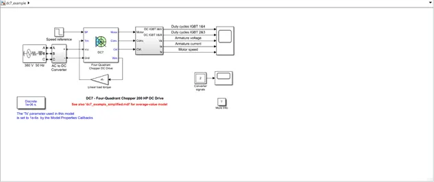
This chopper has a power rating of 200HP and it is operated with a constant 150V DC field voltage and is separately excited. The armature voltage is provided by an IGBT converter controlled by two PI regulators. The converter is inputted by a 380V AC 50 Hz voltage source and a braking chopper has been added between the DC7 chopper block and the diode rectifier block to limit DC bus voltage during dynamic braking mode.
The first regulator is a speed regulator and the second is a current regulator. The speed regulator determines the electromagnetic torque required to reach the desired speed and outputs the armature current reference used by the current controller.
There are acceleration and deceleration spikes in the system to avoid armature over-current that causes destabilization. The current regulator controls the armature current by appropriately determining the duty cycle ratios. Instantaneous pulse values of IGBT 1 and 4 are opposite to that of 2 and 3 which inculcates good system behavior. This generates the average armature voltage needed to obtain the desired armature current. A smooth inductance is placed in series with the armature circuit to limit the amplitude of current oscillations.
H-bridge circuit:
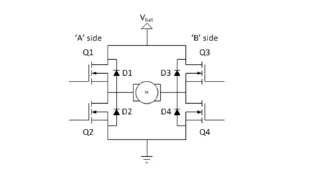
An H-bridge is a simple circuit that lets you control a DC motor to operate in a given direction. It consists of 4 switches and a DC motor.
If switches 1 and 4 are closed, the motor starts running in one direction but if switches 2 and 3 are closed then the motor will start spinning in another direction.
2.
Aim: To develop a 2-quadrant chopper in Simulink and explain the working of the same with relevant results.
Principle and operation:
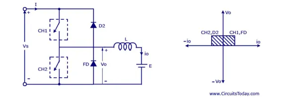
The above figure represents a 2-Quadrant chopper. We require 2-Quadrant operation sometimes by retaining the current direction in both motoring and braking modes. There is a polarity change in terminal voltage keeping the direction of current constant. CH1 and CH2 are the choppers and FD and D2 are the feedback diodes.
When they are ON, the load current increases and it is dependant upon the back emf and torque of the machine. When they are OFF, the load current decreases and this affects the load voltage of the diodes.
MATLAB simulation and results:
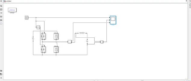
As per the simulation, the blocks used are powergui, pulse generator, voltage source, MOSFETs and diodes, current measurement, voltage measurement, Series RLC circuit with only inductor values and scope.
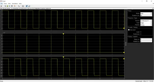
When we input the voltage source with 24V and the pulse generator operates at a duty cycle of 50 %, the voltage source connected in series with the inductor has a value of 12V, the scope shows the following results.
The first plot is from the pulse generator, the second plot is from the voltage measurement across the inductor and the third plot is from the current measurement of the MOSFET and diodes.
We observe a pulsating, repetitive output for all the 3 plots which indicates the ON and OFF conditions of a chopper
3.
Aim: To explain the operation and working of a BLDC motor.
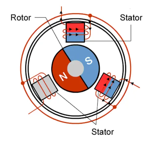
Principle and working: BLDC motor is an electric motor that is driven by DC power and is synchronized by permanent magnets. It deploys an electric commutation which is the production of rotational torque by changing phase currents at regular time intervals, which is different from a mechanical commutation system.
They are more efficient than brushed type DC motors by almost 15-20%
The BLDC motor works on the principle of Lorentz Law which states that whenever a current-carrying conductor is placed in a magnetic field, it experiences a force and the magnet will experience an opposing and equal force.
The permanent magnet moves and the current-carrying coil is stationary. When the stator coils are given excitation by a supply, then it becomes an electromagnet and starts producing a uniform field. Even though the supply is DC, switching makes to generates an AC voltage waveform. Due to the magnetic force between stator and rotor, the rotor continues to rotate.
Circuit diagram:
Construction:
Most BLDC motors that are used are 3 phase and the components are as follows:
- Stator: They are made up of laminations to hold the windings and are made up of steel. The windings are slotted in an axial manner and cut across the stator. The windings can either be star or delta. Most BLDC motors have 3 phase star connected stator
- Rotor: Permanent magnets are used in the rotor. There are alternating south and north poles depending on the application requirement Flux density of the material should be high to achieve maximum torque.
- Hall effect sensor: It synchronizes stator armature excitation with rotor position. It arranges the stator windings in a sequential order to rotate the motor. It senses the rotor position.
Advantages:
They are highly efficient due to the permanent magnet rotor and they are relatively light compared to brushed DC motors and AC motors. They tend to have a long lifespan.