Week - 4
Aim:
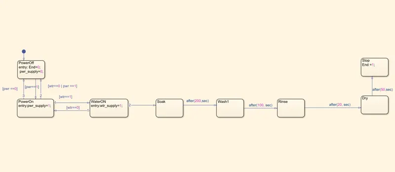
- Implement control logic of a “washing machine” using Stateflow as per given sequence:
Objective:
- If the power supply is available, the system gets activated
- If the Water supply is not available, stop the process & indicate through LED
- Soaking time should be 200s followed by Washing time of 100s.
- Then rinsing happens for the next 20s & dryer runs for 50s
Block Diagram:
1. The Stateflow and control logic of the washing machine to accomplish the given objectives:
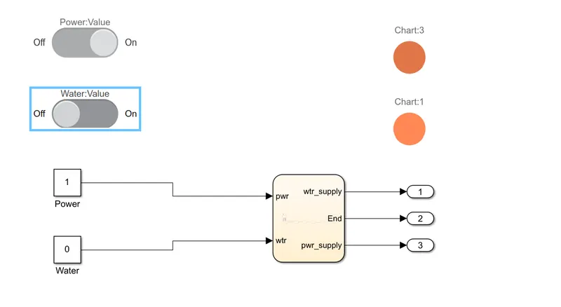
2. Case 1: When the power supply is ON and the water supply is OFF: The washing machine does not function if there is no water
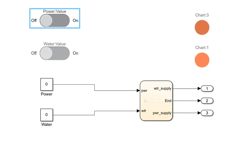
3. Case 2: When both the power supply and water supply are OFF
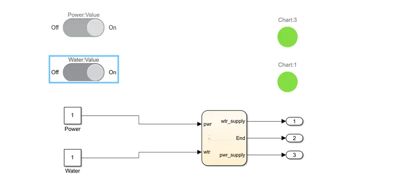
4. Case 3: When both power supply and water supply are ON
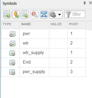
Case 4: Variables from the symbols pane
Explanation:
Here, we are using a slider switch to depict the switching ON and OFF of the power supply or the water supply. We use lamps to depict whether the Power supply and the water supply are either ON or OFF depending on the color ( Green is ON and Orange is OFF ). We use Charts to depict the control logic of the machine. We use constant blocks of values 0 and 1 to signify ON and off conditions of power and water. We use output blocks to get the output of the Washing machine control logic.
Result:
As per the block diagram, initially, the power supply is zero. The system is powered on when the power supply becomes 1( ON condition ). When the power supply is on and the water supply is on, the other processes occur smoothly. Soaking, washing after 200 seconds of soaking, rinsing after 100 seconds of washing, and drying after 20 seconds of rinsing. The washing machine comes to a halt after 50 seconds of drying.
We are able to implement the control logic of a washing machine using Stateflow and depict real-time scenarios. We can alter the data and make changes as required based on the required conditions to simulate accurate results.
2.
Aim: To make a control logic to depict gear shift changes for a speed-range
Objective:
Speed Range(kmph) Gear
0 to 15 1
16 to 25 2
26 to 40 3
41 to 60 4
Above 61 5
Block diagrams and explanation:
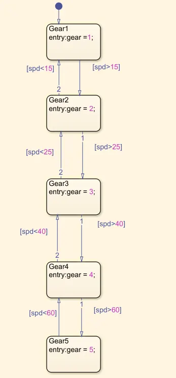
This depicts the gear shift logic for a 5 gear system. If the speed is between 0-15kmph, we use the 1st gear, similarly, if we are at a speed range of 15-25kmph, we use the 2nd gear. 3rd gear if the speed is between 25 to 40kmph, 4th gear if the speed is between 40-60kmph, and 5th gear if the speed is beyond 60kmph.
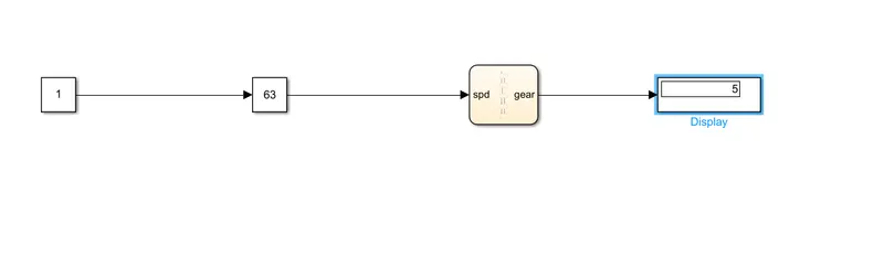
To depict the output, we are using a simple slider gain, connected to a constant block to vary the speed. When you input a speed in the slider gain and run a simulation for a time period, the display shows up the gear which you are currently on for that particular speed. This depiction can also be done with varying speeds to depict the characteristics.
Result:
We can use this to depict any automatic gearbox system with varying parameters. This also represents a real-time simulation of an automotive gear system.