Week -2
Aim: To design a doorbell using a solenoid with Simulink blocks
Objective :
In this setup, when the switch is closed, the electromagnet receives electrical power from the battery and pulls the metal arm to hit the bell producing sound.
To create a situation where the switch is closed for 2 seconds and then released. Observe the physical movement of the plunger.
Block diagrams:
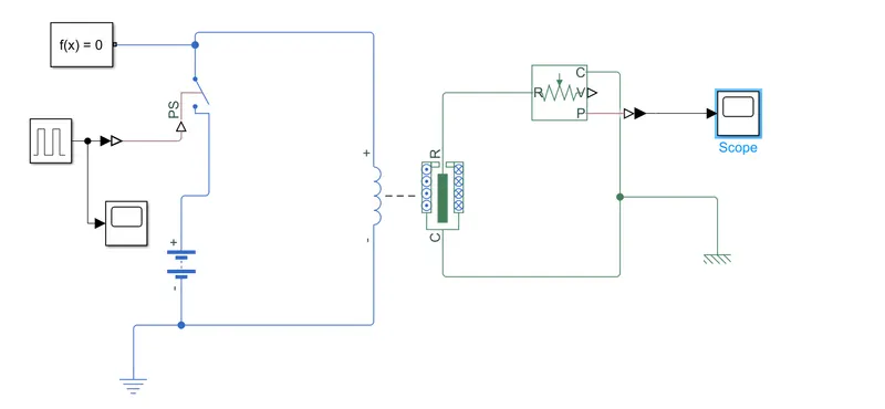
Components used: Solver configuration, pulse generator, scope, Simulink-PS converter, Battery, Switch, Solenoid, Electrical reference, Mechanical reference, and an Ideal translational motion sensor to get the output
The pulse generator is used to provide input to the switch, by using a Simulink-PS converter. A battery is connected to the switch and solenoid to complete the circuit.
Results:
Input scope:
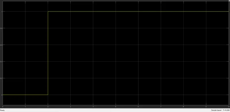
After a time period of 2 seconds, the switch is in an open state as per the graph
Output scope:
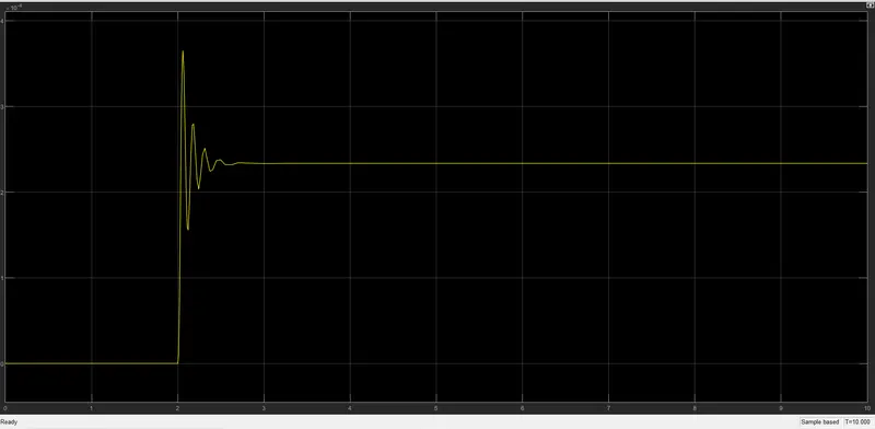
After a time period of 2 seconds, we use an ideal translation motion sensor to replicate the sound produced by the bell.
Conclusion: We can hereby conclude that physical entities can be virtually depicted on Simulink, and replicated as per real-time scenarios. In this case, we do not use a bell, but a translational motion sensor to picture the output characteristics.
2
Aim: Use a thermistor to sense the temperature of a heater and turn on or turn off the fan as per the below conditions
Objective:
To create a Simulink project with the following parameters:
Temperature source: 20 °C from 0 to 10 seconds, 27 °C from 10 to 30 seconds, 23 °C from 30 to 50 seconds
Fan conditions: ON if the temperature above 25 °C, OFF otherwise
Block diagrams:
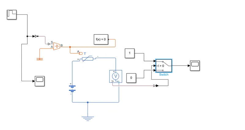
Components used: Repeating sequence stair, Simulink-PS converter, Controlled temperature source with thermal reference to provide the input parameters to the thermistor, Solver configuration, Battery, Voltage sensor, Electrical reference, Switch, Constant blocks, PS-Simulink converter, Scope.
Results:
Input Scope:
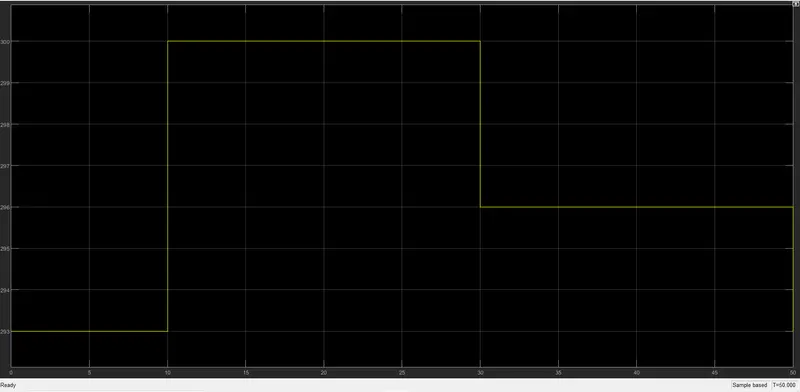
As per the input, the temperature is calculated in Kelvin: From 0-10 seconds, the temperature is 20 degrees Celsius, 27 degrees from 10-30 seconds, and 23 degrees from 30-50 seconds.
Output scope:
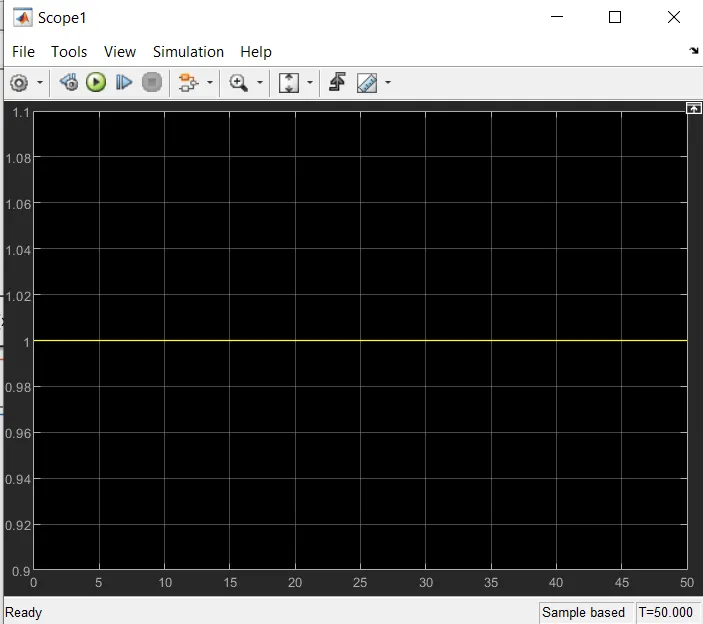
This indicates that the fan is in ON state.
Conclusion: We can hereby conclude that we can design a thermistor set up to sense the temperature of a heater for certain given input conditions. When the heater reaches above 25 degrees, the fan is switched on to provide cooling. Otherwise, it remains off.