Week-6 Challenge: EV Drivetrain
Aim: To discuss the power converter circuits used in an EV or HEV
Types of power converters:
- DC-DC converters (Step-up, Step-down): DC-DC Converters convert an unregulated DC voltage to a regulated DC voltage or a higher voltage level to a lower voltage level or vice-versa. The voltage can be boosted or chopped based on the requirements. They are deployed in situations where power needs to be altered and voltage needs to be kept constant (i.e., throttling in an EV). The type of DC-DC converters used in an EV/HEV depends on the power rating of the motor, vehicle dynamic characteristics. Buck converters reduce high DC to a lower DC voltage, boost converters increase a lower DC voltage to a higher DC voltage. Buck-boost converters perform both buck and boost operations and are a more compact and efficient option when compared to using both buck and boost converters separately. Cuk converters are used to reduce the ripples in the converter.
- AC-DC converters: These converters convert an alternating supply to a direct supply. Chargers used for EV and HEV use these converters. These converters consist of step-down transformers, rectifiers, input filters, and linear voltage circuits. The step-down transformer reduces the voltage from the AC supply to meet our requirements. The input filter is for the surge protection of the device. The rectifier is used to amplify, boost and reduce the losses in the voltage and then is sent to the DC load required to charge the EV.
- DC-AC inverters: Converts DC voltage to AC voltage. The converter used to transmit voltage from the battery pack to the motor is a DC-AC inverter. These inverters consist of capacitors, 6 thyristors, and diodes. Thyristor 1 and 2 are in on and off-state respectively to pass the positive half cycle and the negative half cycle and reverse voltage is protected by the diode. The other thyristor operation is altered by controlling the gate supply to produce an ac voltage supply with a 120-degree phase difference. This voltage is as required by the 3phase motor used in the electric vehicle
Given:
Battery pack voltage(V) = 72V
Armature current = 400A
Armature resistance (Ra) = 0.5ohm
Motor constant (KPhi) = 0.7
Chopper switching frequency = 400Hz
Duty cycle = 70%
Solution:
EV voltage (Vev) = Battery voltage * duty cycle
= 50.4V
Torque equation is given by:
Tev = ( Vev-w*Kphi)*kphi)/Ra
Where w is the EV steady state speed which is to be determined
Tev = ((50.04- 0.7*w) *0.7)/0.5
Tev = 70.56-0.98*w
Tev = 24.7+0.0051*w^2(Given)
70.56-0.98*w = 24.7+0.0051*w^2
i.e 0.0051*w^2+ 0.98*w-46.94= 0
By solving this equation, we get w = 38.85 rad/s and -230.95 rad/s
Neglecting the negative value, we get w = 38.85 rad/s
Q3.
Aim: To develop a mathematical model of a DC motor for the below equation using Simulink.
Ww= V/Kϕϕ -Ra/Kϕϕ^2 .T
MATLAB Model with results:
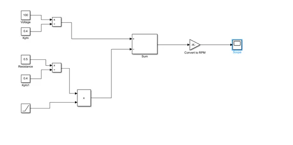
For modeling purposes, we are giving constant values to voltage, motor constant and are assuming it to be 0.4 for this simulation. We are using division, product, and sum blocks. Finally, we use the gain block to convert the same to RPM by multiplying the value with 60/2*pi.
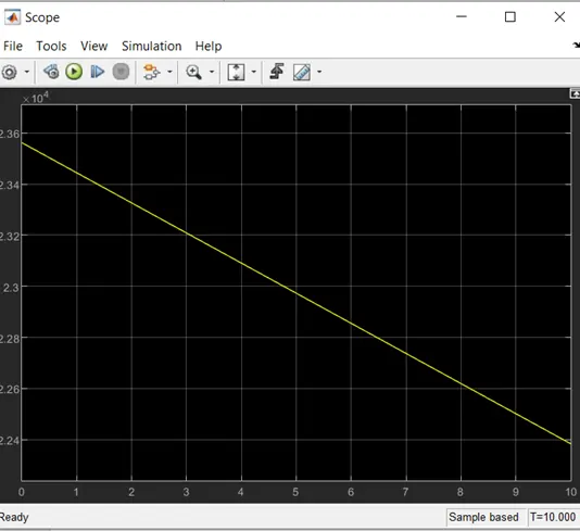
From the following graph, which is plotted between torque and speed, we can observe that torque and speed are inversely proportional to each other.
Q3.
Author’s perspective:
- The author talks about how there are different types of IC engines developed with different configurations like flat-heads, Hemis, straight, opposed, and V configurations, and different engines are developed based on the car type and personal requirements. The same holds good for electric vehicle drives too.
- He then talks about the developments in the electrification industry where it was initially lead-acid batteries and brush motors but now leads have been replaced with lithium battery packs and the motors used are brushless or induction. Controllers have been replaced with modulating inverters to save power. The author cannot choose sides on induction or brushless as he sees both being potentially used for electric vehicles each having its own advantages and disadvantages.
- For brushless motors, permanent magnets in the rotor generate a magnetic field, which enters the stator core and interacts with the current in the windings to produce torque. While the rotor is rotating, we need to make sure that the magnitude and polarity of stator currents are continuously varied- such that the torque remains constant without any losses. The conversion of mechanical to electrical energy should be efficient and the current can be controlled by the use of an inverter. An inverter is the main component in a brushless motor and is useless without it.
- When it comes to induction motors, they have stacked steel laminations with buried peripheral conductors that form a shorted structure that is proportional to the speed difference between the rotor and electrical frequency. Currents produced within the rotor conductors are approximately proportionate to the voltage which creates the speed difference. These currents interact with the magnetic field and then produce the desired rotor torque.
No inverter is needed to start a 3-phase induction motor that has the ability to start under load. Induction motors are compatible with conventional utility power and are the main reason for their success. Brushless motors produce no starting torque when directly connected to a fixed frequency utility power. An inverter whose phase is maintained in step with the angular position of the rotor is required.
- The drawback of a 3-phase induction motor is that it cannot operate from DC. They are constant speed machines as the speed is proportional to frequency. When operated from utility power, they have limited starting torque and somewhat limited running peak torque capabilities when compared to DC machines.
- The difference between brushless and induction are the rotors and the inverter controls. Less rotor heat is generated in the brushless. They can operate in unity power factor whereas, for induction drive, it’s about 85%. The strength of MF can be adjusted. Induction machines are difficult to control and achieving stability is more difficult here.
- There is still no clear winner when it comes to these but there could be a hybrid of induction and brushless motors working side by side in the golden era of hybrid and electric vehicles.