Week-7 Challenge: DC Motor Control
1. A. Explain a MATLAB demo model named ‘Speed control of a DC motor using BJT H-bridge’.
Matlab Demo:
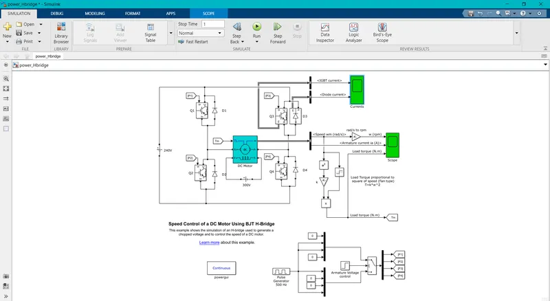
Explanation:
An H-bridge is an arrangement of transistors that allows a circuit full control over a standard electric DC motor. That is, an H-bridge allows a microcontroller, logic chip, or remote control to electronically command the motor to go forward, reverse, brake, and coast.
Four BJT's are Used to form a h-bridge by onnecting two bjt in a series in a leg, Two sets of Bjt's are connected in Parallel to each other.
This H-Bridge circuit forms chopper that works on four Quadrants,Such as Forward Motoring,Reverse Motoring,Forward Braking & Reverse Braking.
When the BJT Q1 & Q4 are turned on the positive voltage is passed through the load and the diode D1 & D4 acts as free wheeling diode.
When the BJT Q2 & Q3 are turned on the negative voltage is passed through the load and the diodes D2 & D3 acts as Free Wheeling Diode.
By Changing the Firing Angle Of the BJT the current level is also Limited and thus the Speed control Of a DC Motor is done Using BJT-Hbridge.
Output Result:
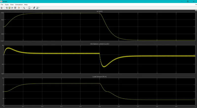
B. Comment on the armature current shoot-up from the scope results.

We could see a suden increase of Current in the Armature as because of the Switching Transients of the Semiconductor Switches.
When the Switches are turned on a switching transient is been created because of energy stored in the inductor, thus a current surge is occured.
When the Switches are turned off the energy stored in the Inductor Gets discharged so a sudden hike in current is occured.
Thus this Suddent Armature shoot up current can be reduced by changing the duty cycle ratio as 50%.
C. Refer to the help section of ‘The Four-Quadrant Chopper DC Drive (DC7) block’. Compare it with the H-bridge model:
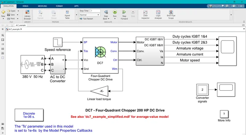
Four Quadrant Chopper Model:
Observations:
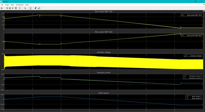
Operation Of a four Quadrant Chopper:
The Four Quadrant chopper or Class E Chopper Works in All four Quadrants present in a graph.
The Operating Four Quadrants Are :
Forward Motoring
Forward Braking
Reverse Motoring
Reverse Braking
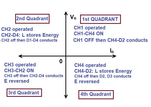
In a four Quadrant chopper there are Four chopper switches used in it.
When the Chopper (CH1&CH4) are turned On it Works in 1st Quadrant That is Forward Motoring Region.
When the Chopper (CH2) is turned On the Inductor Charges Through conduction path of Ch2 & D4,When The CH2 is Off then the Energy Stored in the Inductor Passes through The Diodes D1 & D4. Thus it Works in 2nd Quadrant that is Forward Braking Region.
When the Chopper (CH3&CH2) are turned On it Works in 1st Quadrant That is Reverse Motoring Region.
When the Chopper (CH4) is turned On the Inductor Charges Through conduction path of Ch4 & D2,When The CH4 is Off then the Energy Stored in the Inductor Passes through The Diodes D2 & D3. Thus it Works in 4th Quadrant that is Reverse Braking Region.
BJT H-Bridge:
This type of converter is used for 2 Quadrant Operation of a graphical Representation.
The Operating Quadrants are 1st Quadrantb & 3rd Quadrant.The Operating regions are:
Forwar Motoring Region
Reverse Motoring Region
When Q1 and Q3 are turned On thus the Diode D1 and D3 works as a free Wheeling Diode thus it Works in 1st Quadrant as the positive voltage is passed through the load and thus it works in Forward Motoring Region.
When Q2 and Q4 are turned On thus the Diode D2 and D4 works as a free Wheeling Diode thus it Works in 3rd Quadrant as the negative voltage is passed through the load and thus it works in Reverse Motoring Region.
Result:
Thus by comparing Both Four Quadrant Chopper and BJT H-Bridge The Four Quadrant chopper or (Class E) chopper Operates in all Four Regions, Whereas the BJT H-Bridge Works only in 3 Quadrants and one Costal Region.
2. Develop a 2-quadrant chopper using simulink & explain the working of the same with the relevant results:
Simulink Model:
Output Results:
Working:
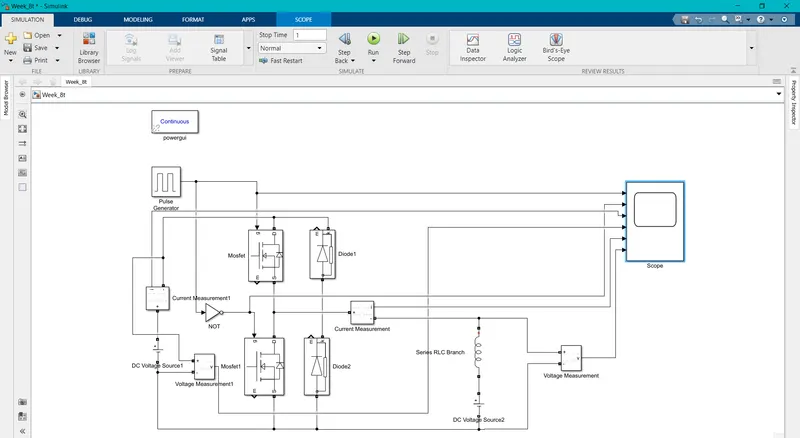
A Pulse Generator is used to produce Gate Signal for the Switching devices.A set of switches requires positive signal whereas another set of switches requires negative signal.
So a Logic Gates are used to get such type of Signals from one Signal produced.Thus a NOT Gate is used to convert the pulse generated from the pulse Generator.
Two MOSFET and Two Diodes are used each in Parallel to each other thus forms a h bridge by connecting a inductive load with a back EMF.
Thus the Input & Output Voltages and currents are measured using voltage measurement blocks and current measurement blocks.
Thus it is connected to a scope to find out the measurements in graphical representation.
Thus the Gate Signals are also connected to the Scope to Know the Pulse given to the Gate.
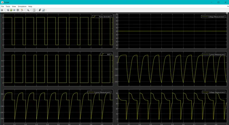
When MOSFET Q1 is turned On and Diode D2 is in forward Bias thus inductor stores a charge and the Motor runs in Forward direction.
When the MOSFET Q2 is turned on and DIODE D1 is in forward bias the charge in the Inductor Flows through the Freewheeking Diode.Thus the Motor runs in Reverse direction.
Thus the 2 Quadrant chopper Works only on the 2 Quadrants such as Forward Motoring and Reverse Motoring.
3. Explain in a brief about operation of BLDC motor:
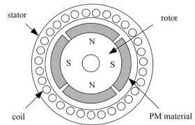
BLDC motor works on the principle similar to that of a conventional DC motor, i.e., the Lorentz force law which states that whenever a current carrying conductor placed in a magnetic field it experiences a force. As a consequence of reaction force, the magnet will experience an equal and opposite force. In case BLDC motor, the current carrying conductor is stationary while the permanent magnet moves.
When the stator coils are electrically switched by a supply source, it becomes electromagnet and starts producing the uniform field in the air gap. Though the source of supply is DC, switching makes to generate an AC voltage waveform with trapezoidal shape. Due to the force of interaction between electromagnet stator and permanent magnet rotor, the rotor continues to rotate.
Consider the figure below in which motor stator is excited based on different switching states. With the switching of windings as High and Low signals, corresponding winding energized as North and South poles. The permanent magnet rotor with North and South poles align with stator poles causing motor to rotate.
Observe that motor produces torque because of the development of attraction forces (when North-South or South-North alignment) and repulsion forces (when North-North or South-South alignment). By this way motor moves in a clockwise direction.
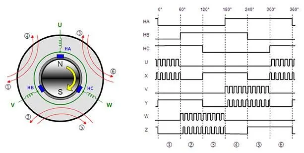
Based on this signal from sensor, the controller decides particular coils to energize. Hall-effect sensors generate Low and High level signals whenever rotor poles pass near to it. These signals determine the position of the shaft.
Brushless Motor Drive:
As described above that the electronic controller circuit energizes appropriate motor winding by turning transistor or other solid state switches to rotate the motor continuously. The figure below shows the simple BLDC motor drive circuit which consists of MOSFET bridge (also called as inverter bridge), electronic controller, hall effect sensor and BLDC motor.
Here, Hall-effect sensors are used for position and speed feedback. The electronic controller can be a microcontroller unit or microprocessor or DSP processor or FPGA unit or any other controller. This controller receives these signals, processes them and sends the control signals to the MOSFET driver circuit.
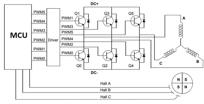
Thus The BLDC Motor and BLDC motor Drive Works.