Week - 4
1)
Aim:
To implement control logic of a "washing machine" using stateflow as per given steps.
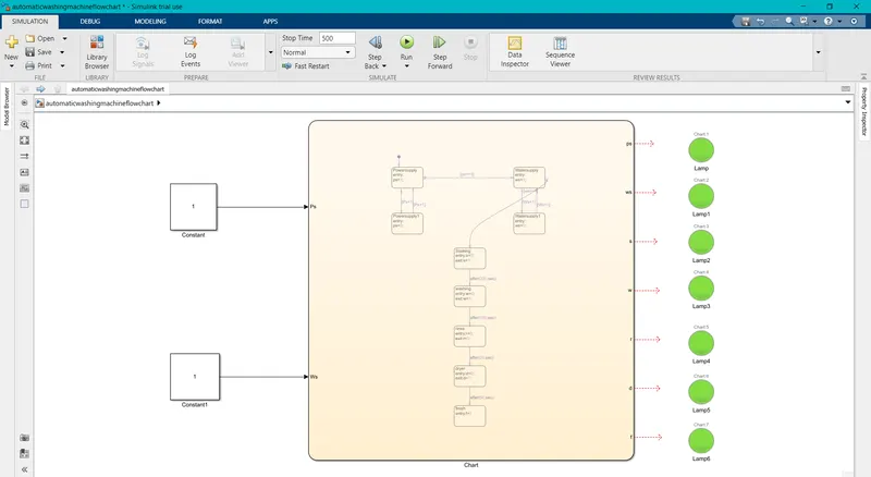
Simulink Blockdiagram:
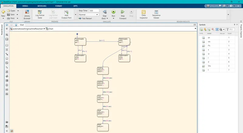
Stateflow chart:
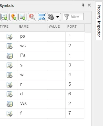
Input & Output parameters:
Step by Step Working Process:
1) If the powersupply is availabe.The system gets activate.
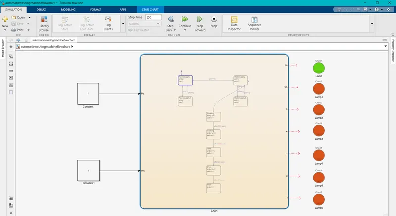
2) If the water supply is not available,stop the process and indicate through led:
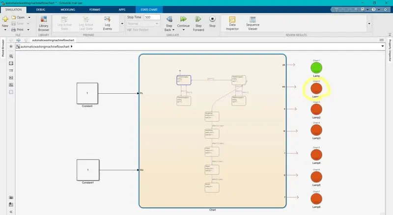
3)soaking time should be of 200s followed by washing time of 100s.
Soaking time of 200sec.
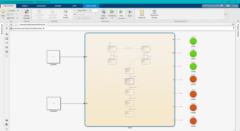
washing time of 100sec.:
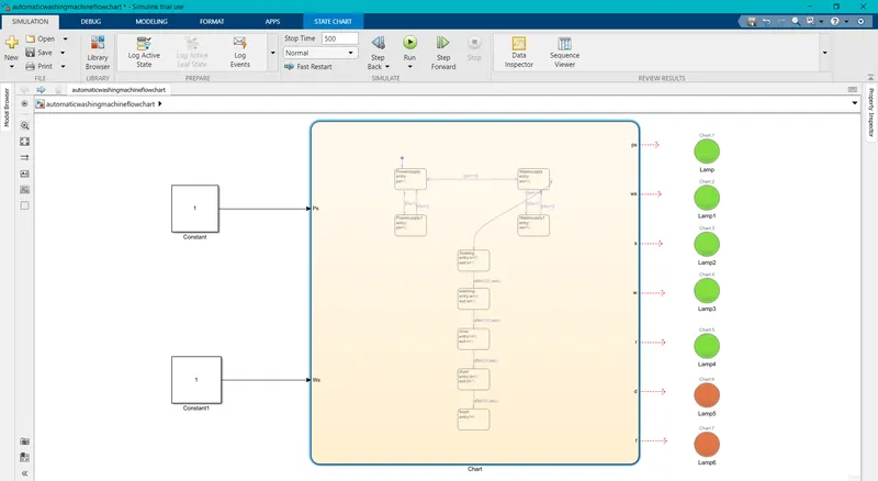
4)Then rinsing happens for 20sec & dryer runs for 50 sec.
Rinsing for 20 sec:
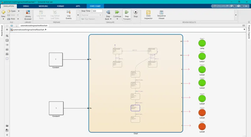
Dryer for 50 sec:
Result:
Thus the simulink flowchart has been implemented for the "Automatic washing machine" and thus the conditions have been satisfied.
2)
Aim:
To make a simulink chart for the "Gear shift"logic as per some conditions.
Simulink block diagram:
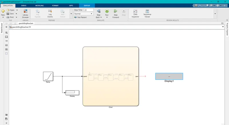
Simulink Chart:
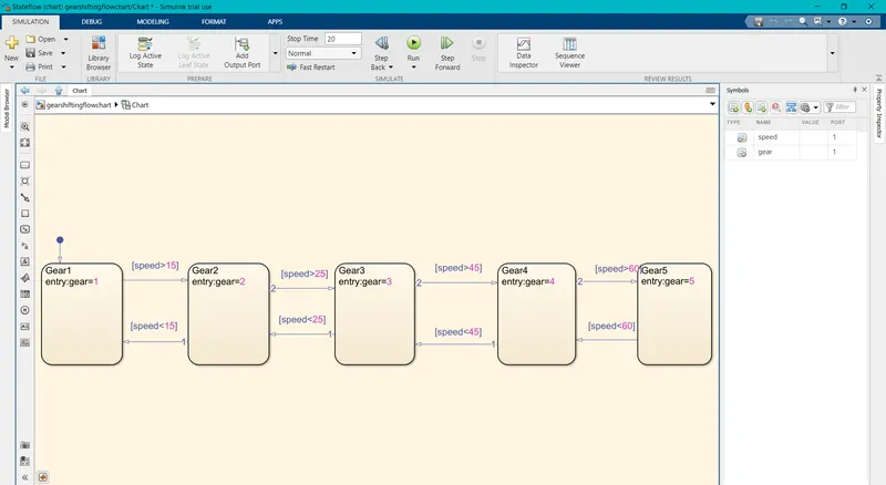
Step by Step process:
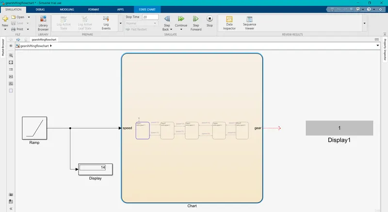
1)Speed range is 0-15 kmph the gear should be 1.
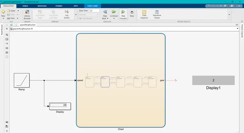
2)If the speed range is 16-25 the gear should be shifted to 2.
3)If the speed range is 26-40 the gear should be shifted to 3.
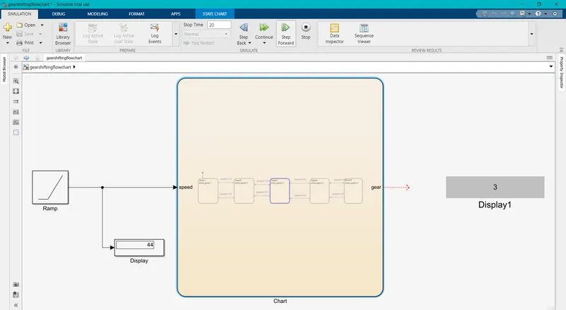
4)If the speed range is 41-60 kmph the gear should be shifted to 4.
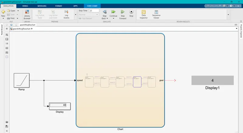
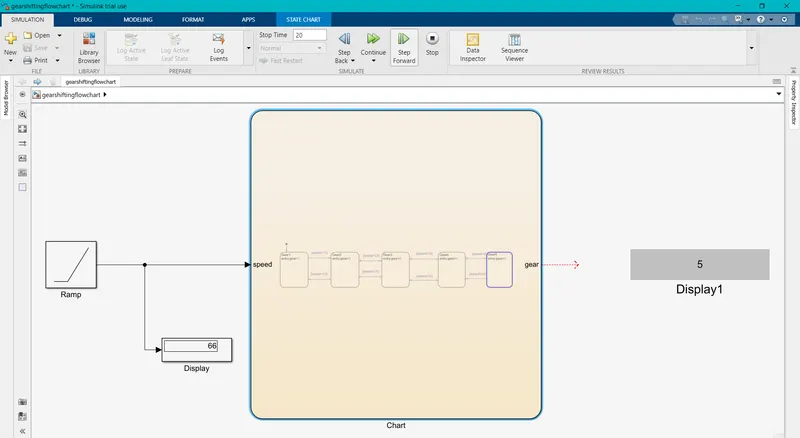
5)If the speed range is above 61 the gear should be shifted to 5.
Result:
Thus the stateflow chart for a gear shifting has been made and satisfied the following conditions.