Week -2
1)
AIM:
To make a simulink model of a Doorbell using solenoid block and observe the physical movement of the plunger where the switch is closed for 2 seconds and released.
SIMULINK BLOCK DIAGRAM:
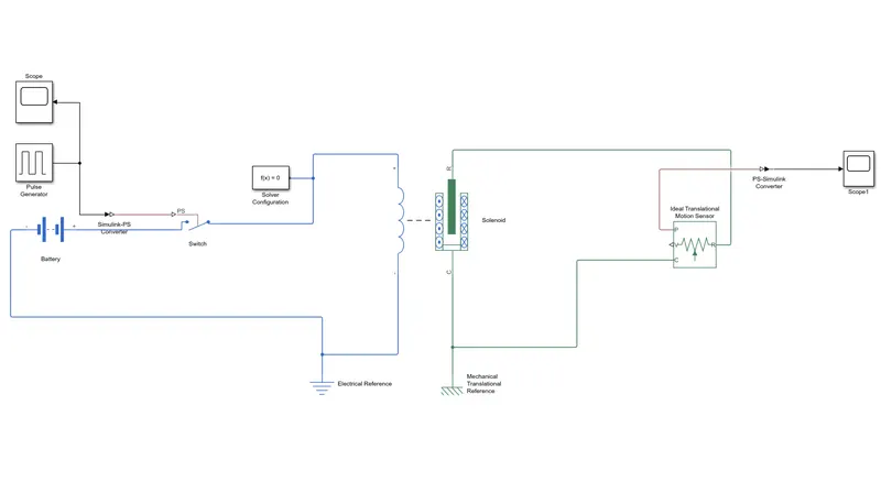
BLOCK DIAGRAM EXPLANATION:
- A battery block is used to supply power to the solenoid block.
- A switch is used to on or off the solenoid coil.
- A pulse generator block is used to give a signal to the switch so that it could get turn on and off for a certain period.
- The pulse generator is configured with period of 4sec,and pulse width is 50% of period that is 2sec,thus the pulse is created for on time of 2 seconds.
- A solver configuration block is used for the solving parameters needed by the simscape model as it contains combination of physical models such as (mechanical,electrical,magnetic,etc...).
- A solenoid block is used by configuring the mechanical parameters so that the plunger attraction value changes.
- An electrical reference and a mechanical translation reference is used.
- An ideal translation motion sensor is used to observe the changes occur in the plunger of solenoid.
- Simulation ps converter is used to convert simulink signal to a physical signal,and ps simulation converter is used to convert physical signal to a simulink signal.
- Two scopes are used one is to observe the input from the pulse generator and another one is to observe the output from the ideal translation motion sensor.
INPUT SIGNAL :
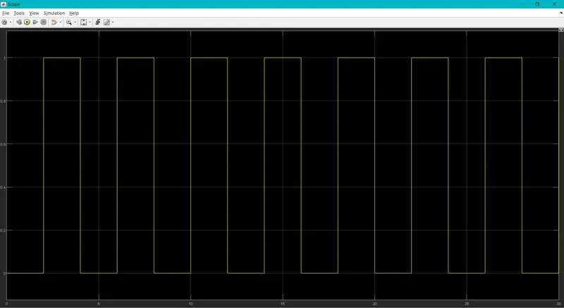
By configuring the parameters of the pulse generator this sinal is obtained.
OUTPUT SIGNAL:
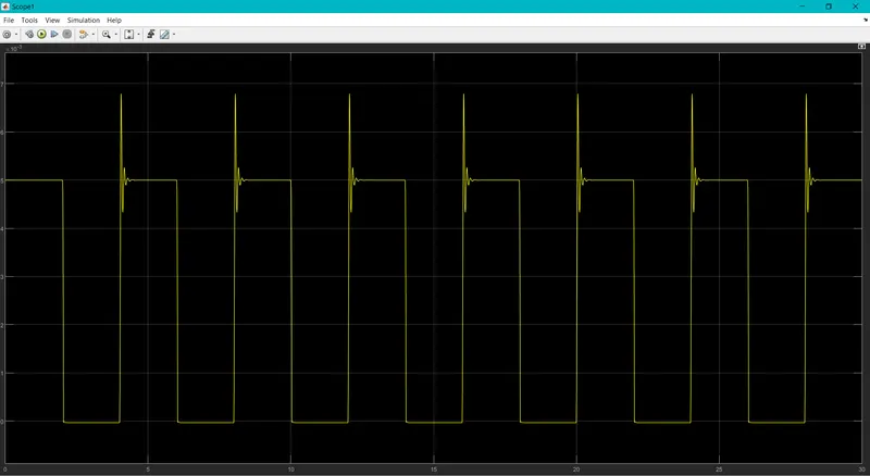
This is the output of plunger's physical movement that is obtained from the ideal translation motion sensor.
CONCLUTION:
Thus the simulink model of a door bell using solenoid block is been made and the physical movement of the plunger is been observed.
2)
AIM:
To use a thermistor to sense the temperature of a heater and turn OFF or ON the fan as per conditions.
CONDITION:
Turn ON the Fan if temperature is above 25°C otherwise turn OFF the Fan.
SIMULINK BLOCK DIAGRAM:
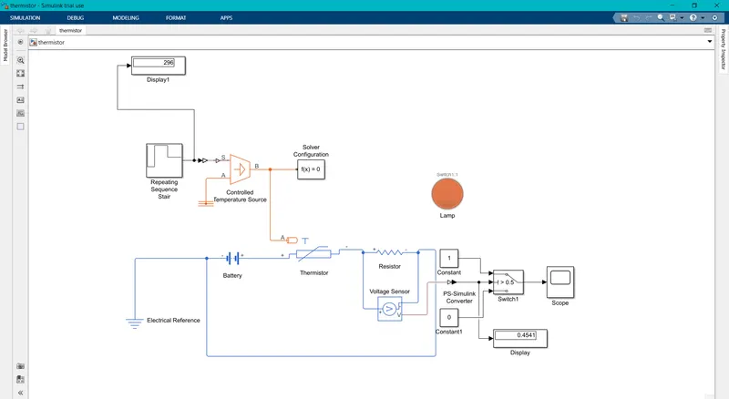
BLOCK DIAGRAM EXPLANATION:
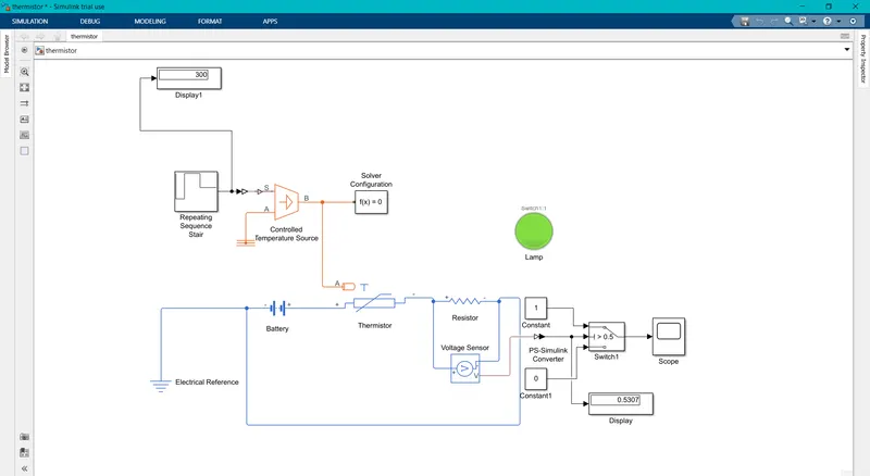
- A Repeating sequence stair block is used to generate various signals that are needed in various time.It is configured with the conditions given as 0-10 sec 293.15°k,20-30 sec 300.15°k,30-50 sec 296.15°k.
- A display is used to get a numerical output from the repeating sequence stair.
- The output of the sequence stair is given through a simulink ps converter to a controlled temperature source.
- The temperature output is given to a thermistor as thermal reference.
- As here combination of systems are used a solver configuration block is used.
- A resistor block is used to disipate the heat and thus it changes the voltage values so a voltage sensor is used o sense the voltage output.
- Thus it is given to a combinational switch which has conditions to operate at terminal 1 if the condition doesnt satisfy it works with terminal 2.
- Thus a display is used to get the output from the voltage sensor
- The switch is given a threshold value >0.5 thus if the voltage is above 0.5v it works with terminal 1 which the fan turns on.if it i lesser than 0.5 v then it works with terminal 2 whitch the fan turns off.
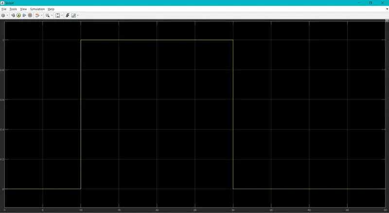
A scope is used to get a graphical output of the signal given in the duration for 50 sec.
OUTPUT:
When the condition is not satisfied :
When the condition is satisfied:
Graphical output from the scope:
RESULT:
Thus a Simulink Model of using a thermistor to sense the temperature of the heater and turn off or on the fan as per the conditions.