Week-7 Challenge: DC Motor Control
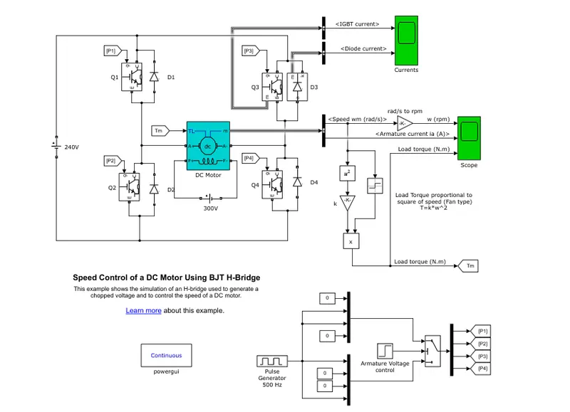
1 ) A) AIM - Explaining a MATLAB demo model named ‘Speed control of a DC motor using BJT H-bridge’.
We can control the speed of the DC motor by simply controlling input voltage to the motor.
Most common method doing that is by using pulse width modulation PWM signal.
PWM is a technique which allows us to adjust the average value of the voltage that is going to the electric device by turning on and off power at the fast rate.
The average voltage depends on the duty cycle or the amount of the time the signal is on versus the amount of time the signal is off in a single period of time.
For controlling the rotation direction we just need to reverse the direction of current flow through the motor and the most common method of doing that is by using an H Bridge.
An H Bridge circuit contains Four switching element such as transistors or more space with the motor at the centre forming ' H ' like configuration by activating to particular switches at the same time.
We can also change the direction of the current flow, this changes the rotation direction of the motor.
So if We combine these two methods PWM and H Bridge we can have a complete control over the DC motor.
WORKING -
In this model h Bridge consists of Four BJT 's and Four Diodes. IGBT acts as the BJT in power switching device ( Q1, Q2, Q3, Q4 ) .
The gate terminals of four IGBT controlled by pulses 0 and 1 given by P1, P2, P3 , P4 according to the armature voltage of Motor given by Pulse generator.
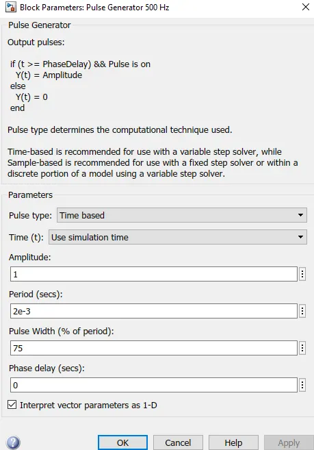
The motor starts in positive direction with duty cycle of 75% equivalent to 180 volt, At = 0.5 sec.
In first step , swhich Q1 and Q4 are forward biased by giving 1 V to IGBT's.
Thus positive voltage is applied to the motor and there for motor rotates in forward direction.
And diode D2 and D3 operates as freewheeling diode when Q1 and Q4 are switched off.
In second step , switches Q2 and Q3 are forward biased by giving 1 volt . Thus negative voltage is applied to the motor and their pole motor rotates in reverse direction.
Diodes D1 and D4 operates as a free wheeling diode when Q2 and Q3 are switched off .
RESULT -
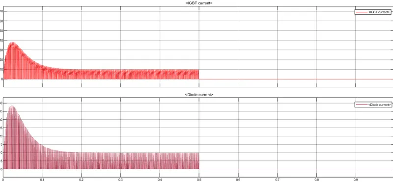
The above graph shows the current passing through IG BD switch Q3 for interval of 0 sec to 0.5 sec and free wheeling diode D3 for the interval of 0.5 sec to 1 second.
B ) Commenting on the armature current shoot-up from the scope results.
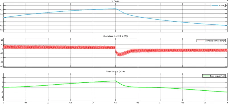
Starting Current shoot up is due to sudden increase in voltage which can be regulated by Duty Cycle.
When the Motor is driven at 75 % duty cycle equivalent to 180 v , the peak value of the current at the starting is 40 A .
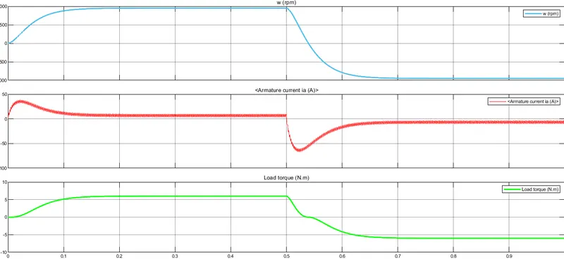
At 50% Duty Cycle , The peak value of the current at starting is 8.5 A.
RESULT -
By Varying Duty cycle from 0 to 100 % or By Varying Voltage , we can control the shoot up armature currents.
C ) Referring to the help section of ‘The Four-Quadrant Chopper DC Drive (DC7) block’. Comparing it with the H-bridge model.
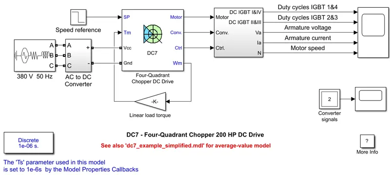
It is four quadrant Chopper drive
It works in four modes.
In first quadrant it works as forward motoring mode.
In second quadrant it works as a regenerative braking mode.
In third quadrant it works at reverse motoring mode.
In fourth quadrant it works as reverse regenerative mode.
An AC to DC Converter is used to rectify 380 V, 50 Hz supply to 515 V DC supply.
The 200 HP DC motor is separately excited with a constant 150 volt dc field voltage source.
A braking chopper is added between the diode rectifier and the DC 7 block in order to limit the DC bus voltage during dynamic braking mode.
To reach the desired speed the needed electromagnetic torque can be obtained by speed regulator which outputs the armature current reference used by the current controller.
The speed reference gradually changes acceleration and deceleration in order to avoid shoot up of armature current.
Comparing -
In four quadrant Chopper drive motor can be operated in four different modes such as forward motoring , reverse motoring, regenerative braking mode, reverse regenerative braking mode .
Whereas h-bridge drive is used for changing the direction of the motor which is forward and reverse mode.
Regenerative braking is not available in h-bridge, whereas it is available in four quadrant Chopper drive.
The motor reference can be fed in case of four quadrant Chopper drive where is in case of h Bridge it cannot be fed.
In case of four quadrant Chopper drive the motor is separately excited with a constant 150 volt dc field voltage source whereas in H bridge the motor is not separately excited.
2 ) AIM - Developing a 2-quadrant chopper using simulink & explain the working of the same with the relevant results.
The two quadrant chopper configurations can be obtained by connecting the single quadrant choppers of type A and type B in parallel.
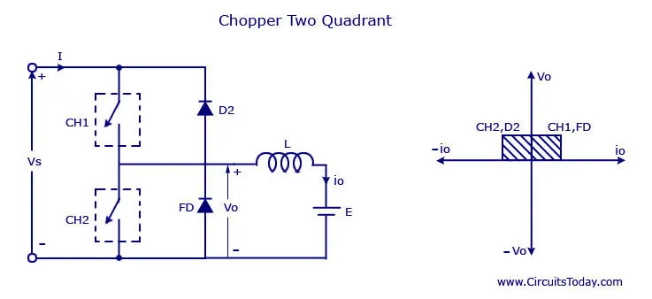
We can use power transistors, SCRs , IGBTs, MOSFETS for chopper operation. The MOSFETs can be represented by switches S1 and S2.
Operation of type C chopper
The switch S1 and D1 form a type A chopper whereas switch S1 and D1 form a type B chopper.
Mode I (S1 Turned ON) -
As soon as switch S1 is turned on the dc supply gets connected across the load making the load voltage positive (Vo = + V).
The load current flows from the dc supply to the load. Thus load voltage and load current are both positive and load receives power from the source.
Mode II (S1 turned OFF / D1 starts conducting) -
As soon as S1 is tumed off, due to sudden interruption of load current, a negative self induced emf (L di / dt) appears across the load inductance.
This will forward bias diode D1 and freewheeling takes place through it. After sometime the freewheeling current reduces to zero, and D1 turns off. Load voltage is zero and load current is positive in this mode of operation.
Mode III (D1 turns OFF / S2 turned ON) -
S2 can be turned on only after D1 goes out of conduction. S2 can be turned on due to the presence of the back emf Eb in the circuit . The load voltage is zero and load current becomes negative in this mode of operation.
Mode IV (S2 turned OFF / D, starts conducting) -
D2 comes into conduction as soon as S2 is turned off. The stored energy is returned back. The motor acts as a generator. The load voltage is positive (Vo = V) but load current is negative in this mode of operation.
Care must be taken to ensure that the two switches S1 and S2 are not turned on simultaneously, otherwise the dc supply will be short circuited. A class C chopper can either work in the first or second quadrant.
Simulink Model -
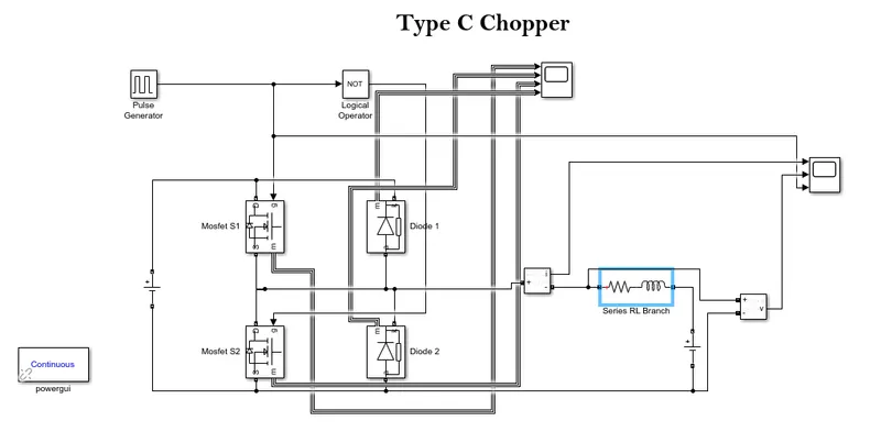
The blockes used are Pulse generator, MOSFETs, Diodes , NOT Gate , RLC Branch,Powergui , Current & Voltage Measurement Blocks.
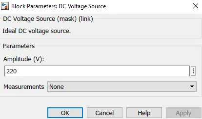
Given voltage source is 220 volts.
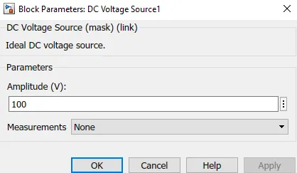
Eb is 100 Volt.
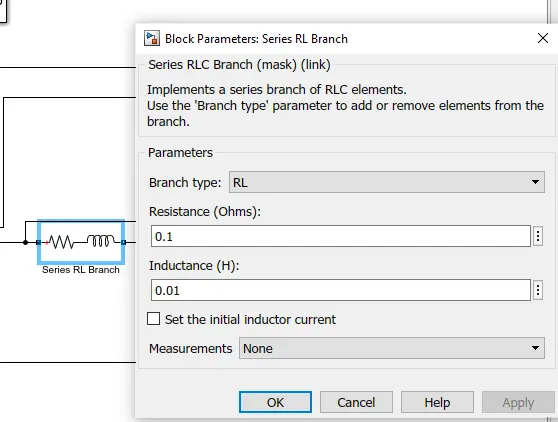
The entered Value of Resistance is 0.1 ohm & Inductance is 0.01 H
NOT Gate is used to ensure that both switches does not conduct simultaneously,if they do so, the supply wil be short circuited.
In PULSE Generator, selected pulse width is 50 % . Because we want 50 % of time to be ON 50 % of time to be OFF.
RESULT -
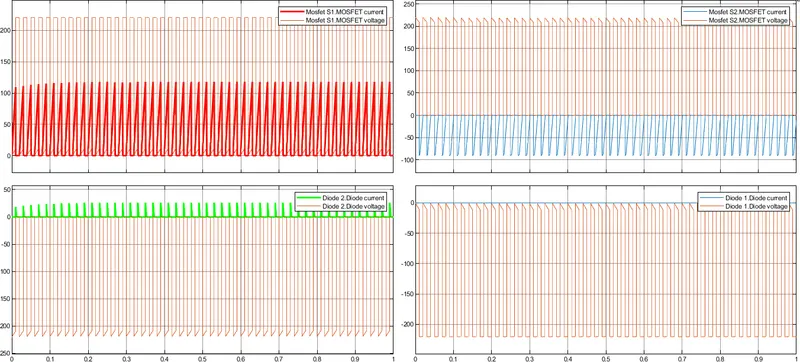
The Above Graph Shows Voltage & Current at MOSFETs & Diodes.
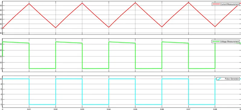
From the Above we can see that , Voltage is Always Positive & Current can either be Positive OR Negative.
3) AIM - Explaining in a brief about operation of BLDC motor.
A brushless DC motor is same as brushed DC motor but bldc doesn't use brushes for commutation but rather they are electronically commutated.
Brushed and brushless DC Motors have main design difference that is replacement of mechanical commutator with an electric switch circuit.
Brushless Motors are available in three configurations such as a single phase , two phase and three phase out of these three phase bldc is the most common one.
Bldc motor consists of two main parts , Stator and Rotor
Stator -
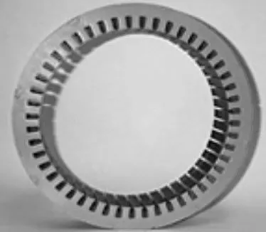
The construction of the stator of a bldc motors is similar to an induction motor.
It is made up of stacked Steel laminations axially cut slots for winding.
The windings in the the bldc are slightly different than windings in induction motor.
Most bldc motors consists of three stator windings that are connected in Star connection without a neutral point.
Rotor -
The rotor part of bldc Motor is made up of permanent magnets such as rare Earth alloy magnets like Neodymium , Samarium Cobalt and alloy of Neodymium ferrite and Borron.
The number of poles can vary between 2 to 8 according to the applications.
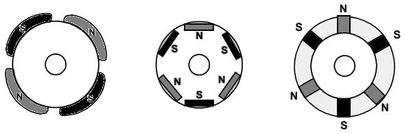
North and South poles are placed alternately in the Rotor or on the Rotor.
Working Principle -
Considering three windings in the stator named as A, B & C.
When stator winding is excited it creates a magnetic pole according to the direction of current.
Using this principle if we supply current to coil a then created magnetic pole will attract the rotors magnet.
Therefore the position of the rotor magnetic will shift slightly clockwise and will try to align with a Coil A.
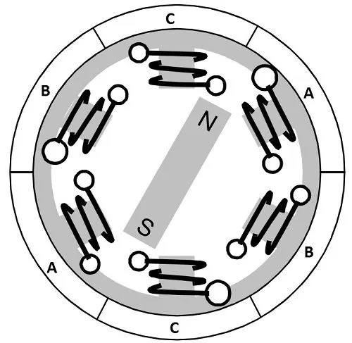
After that if we pass the current through a coil B and C one after the other, then the rotor with rotate in clockwise direction.
We can also wind the opposite coils using a single coil so that we get double attraction.
Energising Two coils at the same time will attract the magnet and the other coil will repel it.
Six Possible combinations of the coils A , B and C are applicable for a complete 360 degree rotation of the rotor magnet.
They are shown in the below timing diagram.
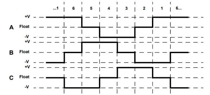
From the above diagram we can see that one page if positive one page is negative and the third stage is idle.
Hall Sensor -
A sensor determines the position of a rotor and based on these information controller decides which coil to energized.
The sensor used for this purpose is called Hall sensor.
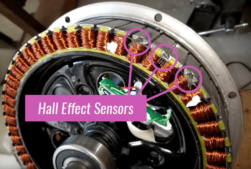
Hall sensor is generally used to detect the position of the rotor and transforms it into an electrical signal.
Advantages of BLDC Motors -
No wear and tear due to absence of brushes.
High efficiency
High dynamic response
Better speed vs torque characteristics
Long life
Less noise or noiseless operation
Significantly higher RPM
Applications of Brushless DC Motors -
Single speed applications
Adjustable speed applications
Electric vehicles, hybrid vehicles, and electric bicycles.
Position control
Low noise applications
Industrial robots, CNC machine tools
High speed applications