Week -2
- Aim - to make a simulink model of solenoid using Solenoid block diagram.
# Solenoid -
A coil with many circular close turns of insulated copper wire forming cylindrical shape is a solenoid.
When the coil is energized it creates magnetic field lines which are spread over solenoid.
To make the magnetic lines dense, the iron core is used.
# There are many applications of solenoid, one of the application is doorbell
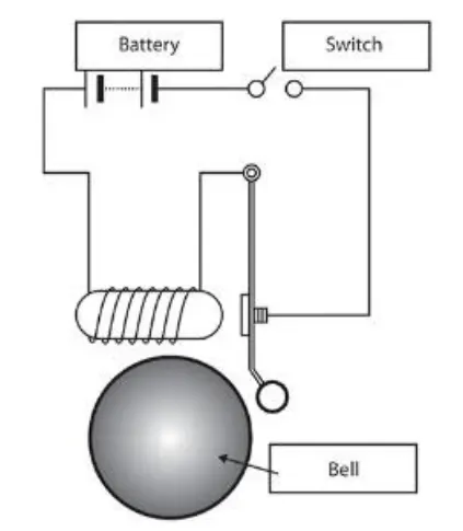
# SIMULINK BLOCK DIAGRAM
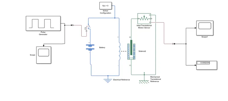
# Simulink Blocks -
Battery - To supply power.
Switch - To on and off the power supply.
Pulse generator - Used to provide pulse.
Solenoid - To work as doorbell.
Ideal translational motion - used to sense translatory motion of the plung.
Electrical reference - Connected to ground the electrical block.
Solver configuration - connected to the circuit for solving the simulation.
Mechanical translational reference - to ground the the Mechanical block.
PS - Simulink converter.
Display and scope.
# WORKING
Pulse generator is connected to switch through a Simulink to PS converter . The switch is in series with battery and solenoid .
When solenoid is energized by battery and Pulse generator, it acts as bar magnet .
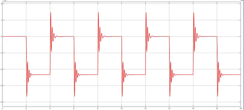
Created magnetic field by bar magnet attracts the arm towards the bail then , ideal translational motion sensor gives the signal proportional to the position. This output is connected to the scope and display through PS to simulink converter.
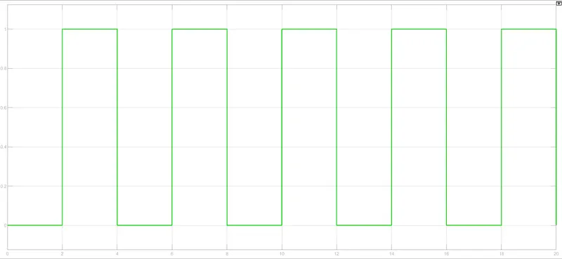
INPUT
OUTPUT
# CONCLUSION
- From this, we understood how to make a simulation of a doorbell using a simulink block.
- And created a situation where the switch is closed for 2 seconds and then released.
2) Aim - To use a thermistor to sense the temperature of a heater & turn on or turn off the fan.
# THERMISTOR
A thermistor is a Temperature sensor whose electrical resistance changes in response to a change in body temperature.
It is used in a variety of different applications and can be viewed as a special type of resistor.
Generally, thermistors are divided into two main types
√ Negative Temperature Coefficient or NTC thermistors.
√ Positive Temperature Coefficient or PTC thermistors.
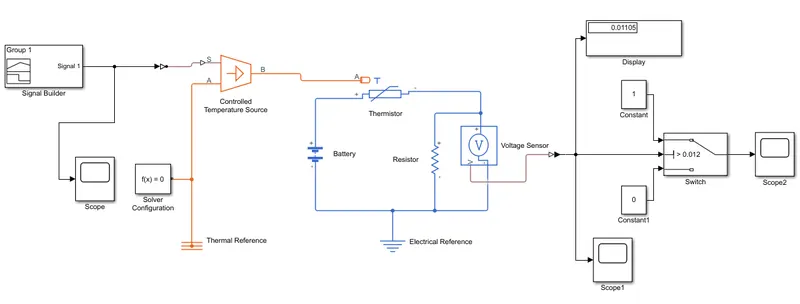
# Simulink block diagram
# Simulink blocks
Signal Builder, PS- Simulink converter, Simulink to PS converter, Thermistor, heater, Voltage sensor, Resistor , switch, display ,scope Battery , Thermal reference , Electrical reference.
WORKING
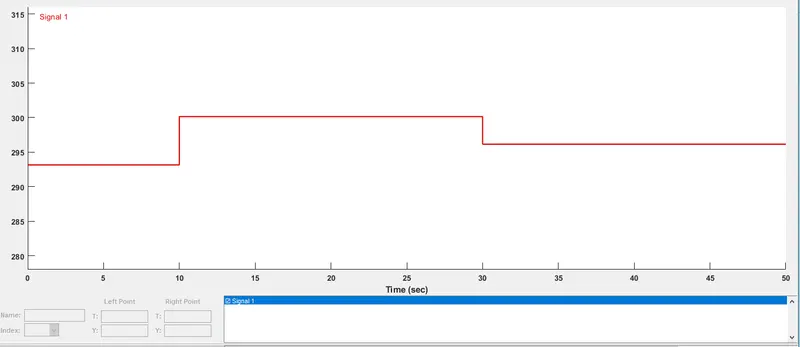
- Signal builder - It is used for creating tests in simulink.
Signal builder Graph
We putted the value as,
For time 0 to 10 seconds the temperature is 293.15 Kelvin
For time 10 to 30 seconds the temperature is 300.15 k.
For time 30 to 50 s the temperature is 296.15 K.
- The simulink - PS converter converts the simulink signal to a physical signal.
- The filtering and derivatives parameter option of the simulink - PS converter block is set to " Filter input derivatives calculated " option.
- After running the simulation the value appeared on the display block is putted in the switch block as the threshold value.
- The FAN will be ON when temperature reaches the value of 298.15 k otherwise it remains OFF.
Following is the output of simulink model.

CONCLUSION
From this simulink model, we understood how the thermistor is used to sense the temperature of the heater and Working of the fan as per the temperature conditions.