Week - 4
Aim - Implement control logic of a “washing machine” using Stateflow.
Block Diagram -
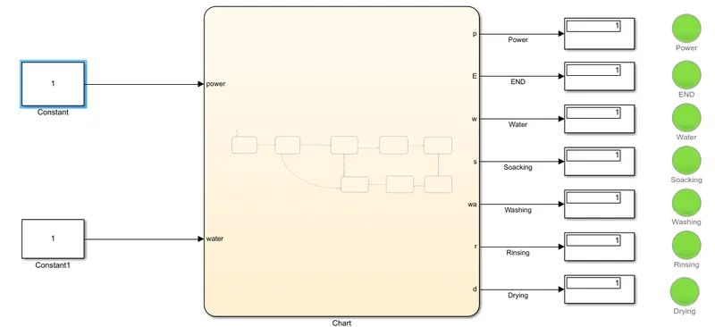
Objective of this simulation is to implement control logic of a washing machine using stateflow.
The blocks used are constants , chart , displays , lamps , indicators.
This System Works on logic control 1 & 0.
StateFlow Chart -
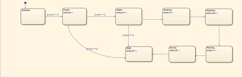
We will perform this simulation as per the given data.
- Power supply is available.
- Water supply is not available.
- Then Soaking , washing , rinsing and drying for given time in seconds.
Power supply is ON -
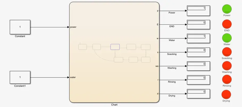
When power supply is ON then , the system gets activated.
When Water supply is not Available -
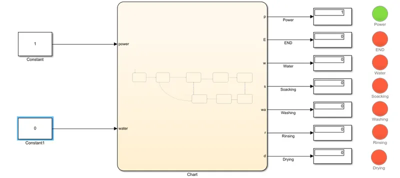
When the water supply is not available then , the whole process will be stop. This is Indicated by ' 0 ' at the output & on the Display.
Soacking Running for 200 seconds -
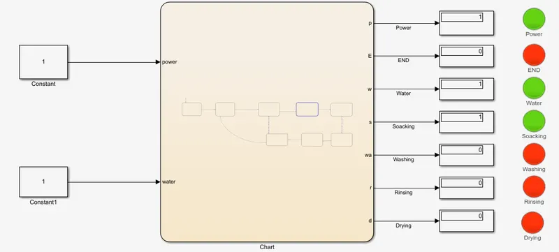
Washing running for 200 seconds -
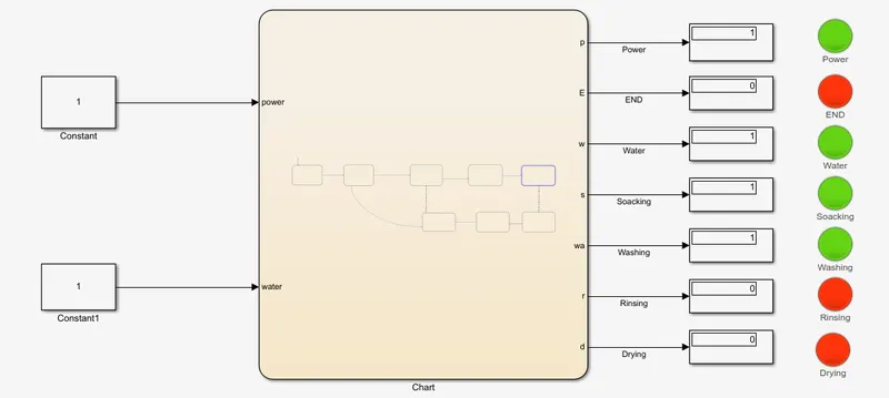
Rinsing running for 20 seconds -
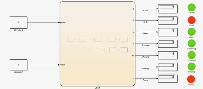
Then Drying running for 50 seconds -
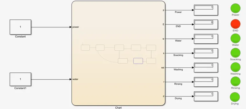
END where the process is completed -
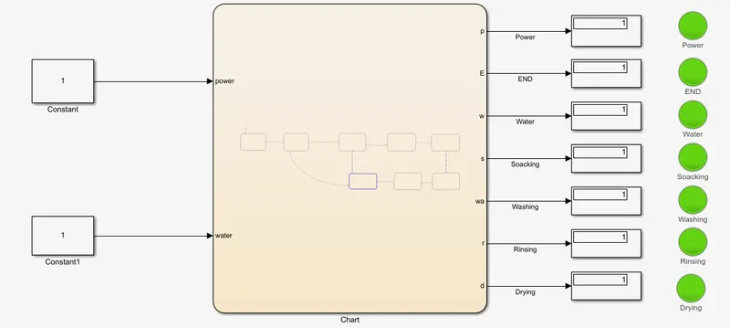
RESULT -
The simulation was Run for 500 seconds.
The machine is ON only when the Both power and water supply are given.
If the water supply is not given then this will affect the whole process (Viewed By Red Light).
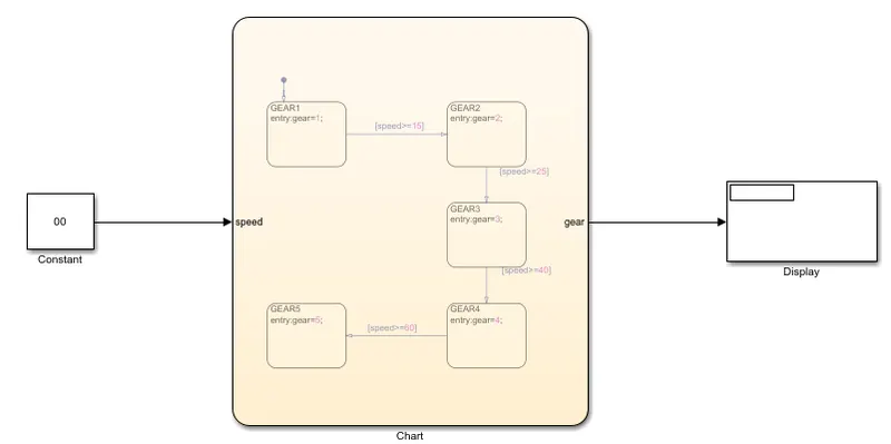
2 ) Aim - Making a Simulink chart for the “Gear shift” logic as per given conditions.
Gear shifting is the process of selecting, engaging, and disengaging Gears for a system for the transmission of power.
By Gear Shifting the RPM of wheels can be varied or the speed of the vehicle can be varied.
The objective of the simulation is to perform the change of gear in response of changing the speed.
BLOCK DIAGRAM -
State flow chart -
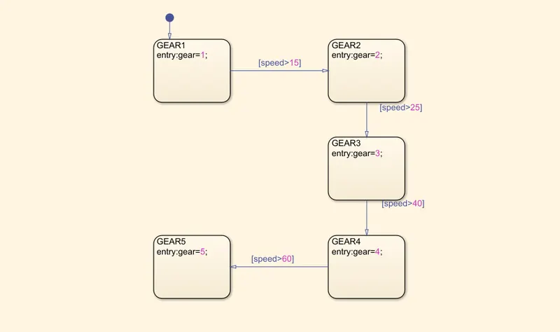
When Speed <=15
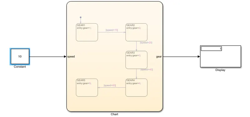
When Speed > 15
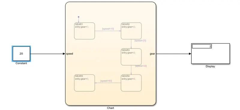
When Speed > 25
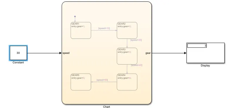
When Speed > 40
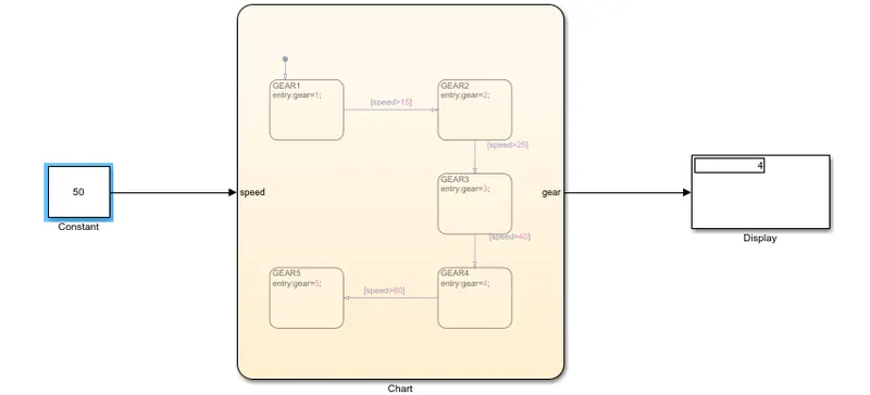
When Speed > 61
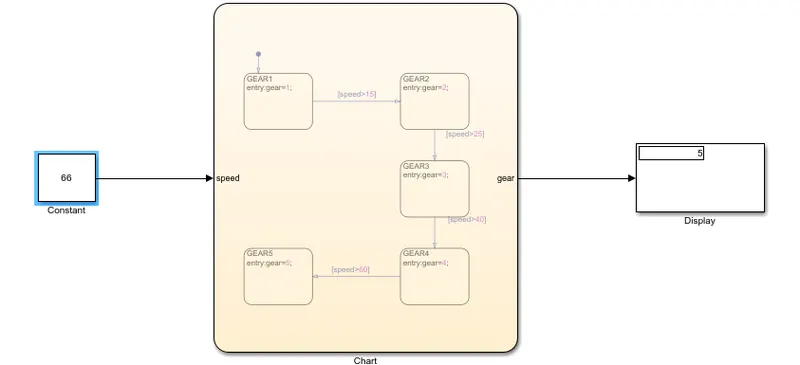
RESULT -
Successfully made a Simulation of Gear shift as per given conditions.
We observed that the gear shift is the function of speed.
'As the Speed changes, Gear changes' !