Week-7 Challenge: DC Motor Control
1. A. Explain a MATLAB demo model named ‘Speed control of a DC motor using BJT H-bridge’.
B. Comment on the armature current shoot-up from the scope results.
C. Refer to the help section of ‘The Four-Quadrant Chopper DC Drive (DC7) block’. Compare it with the H-bridge model.
BJT H-Bridge:
BJT(Bipolor Junction Transistor) when used for power applications,it acts as an IGBT,when it is conducting ,it gives forward bias voltage between the collector and emitter.Therefore IGBT block can be used as a model of BJT device. The IGBT performs by carrying a large amount of load.IGBT can carry more voltage and current parameters.
IGBT(Insulated Gate Bipolor Junction Transistor) block doesnot simulate the gate current controlling the BJT or IGBT.The switch is controlled by a simulink signal.The DC motor uses the pre set model(5HP 24V 1750RPM).It simulates a Fan type load (where torque load is proportional to the square of speed).The armature mean voltage can be varied from 0 to 240V when the duty cycle varies from 0 to 100% which is specified in the pulse generator block.
The H-Bridge consists of a four BJT/Diode (BJT simulated by IGBT models) with the load at the center.Two transistorsare switched simultaneously i.e Q1and Q4 or Q2 and Q3.
When Q1 and Q4 are fired, a positive voltage is applied to the motor D2 and D3 operates as free wheeling diodes when Q1 and Q4 are switched off.When Q2 and Q3 are fired,a negative voltage is applied to the motor D1 and D4 diodes are operates as free wheeling diodes when Q2 and Q3 are switched off.
The four quadrant chopper model was developed in simulink with ideal switches and diodes.A DC machine as connected as the load.The torque of the motor is measured in the closed loop control.The input of the pulse is given to the pulse generator subsystem which inturn giving switching pulses to the four switching elements one after the other.Armature voltage is provided as 240V and the field voltage is given as 300VDC as per the standard specifications of the given model above.i.e 5HP 240V, 1750RPM 300VDC.The switches are triggered with 50% duty cycle.At the output side the speed output is in rad/sec is converted in to RPM.Closed loop control of torque of the motor is implemented.
First quadrant operation :
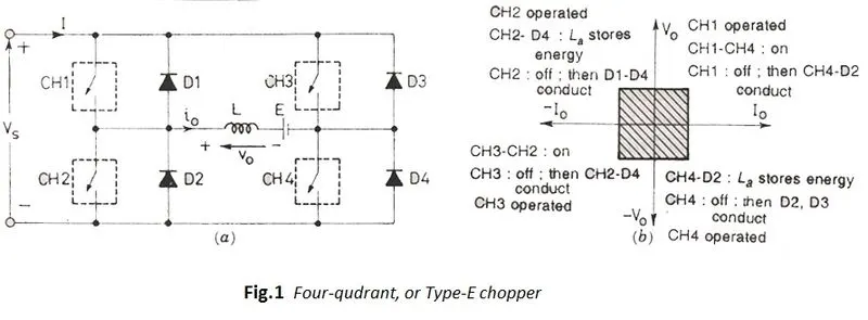
In the first quadrant CH4 is on,CH3 is off and CH1 is operated.When both CH1 and CH4 on simultaneously,the load gets directly connected to the source and hence the output voltage is same as the source voltage.i.e Vo=Vs. since,The source current flows from source to load in the direction of Io.
When Ch1 is off ,the load current free wheels through CH4 and D2.During this period the load voltage and current remain positive.Thus the output voltage and load current are also positive and hence the operation of the chopper is in firstquadrant.So we can see Class E chopper acts as a step down chopper.
Second Quadrant operation:
CH2 is operates while CH1,CH3 and CH4 are kept off.When CH2 is ON,the DC source in the load drives current through CH2 D4,E and L.In this case the inductor L stores the energy.
When CH2 is OFF,the current fed back to the source input through D1 and D4.At this point(E+L.di/dt) is more than the source voltage Vs.As load volltage is positive an Io is negative.Since the current is fed back to the source,the load is transferring from power to the source.
In this case it operates as a step up chopper.
Third quadrant operation:
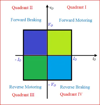
In this case both the load voltage and load current will be negative.The voltage and the current are assumed to be positive if their direction matches which can be seen in the circuit diagram then it is considered as negative.Polarity of EMF,E in the load must be reversed to have third quadrant operation.
The polarity of load EMF,E is reversed
When CH1 is OFF,CH2 is ON and CH3 is operated.When CH3 is ON the load gets connected to the source and hence load voltage is equal to source voltage.But Vo is negative,since the Io is flowing in the opposite direction and hence it is negative.
When CH3 is OFF,the negative load current free wheels through the CH2 and D4.So Vo and Io are both negative.
Fourth quadrant operation:
The CH4 is operated while CH1,CH2 and CH4 are kept off.NOw the polarity of the Load to be reversed,its as it is like third quadrant operation.
When CH4 is ON,then the positive current flows through CH4,D2,L and E,then the energy stores in the inductance L when CH4 is ON.
When the CH4 is Off then the current is fed back to the source through diodes D2 ,D3 hence the load voltage is negative but the load current is always positive.this is the fourth quadrant operation ,since the power is fed back to the source through the load,and hence chopper acts as a step up chopper.
Conclusion:
The operation of four quadrant chopper is summarised by the following diagrams.
Choppers:
A DC chopper also known as DC-DC converter.It is a static device which is used to obtain a variable DC voltage from a constant DC voltage source.A DC-DC converter is a electronic circuit or electromechanical device that converts a source of direct current from one voltage level to other voltage level.It is a type of electric power converter.Power levels range vary from very low i.e small batteries to very high i.e large batteries which carries high voltage power transmission.It has two types i.e step up and step down choppers. 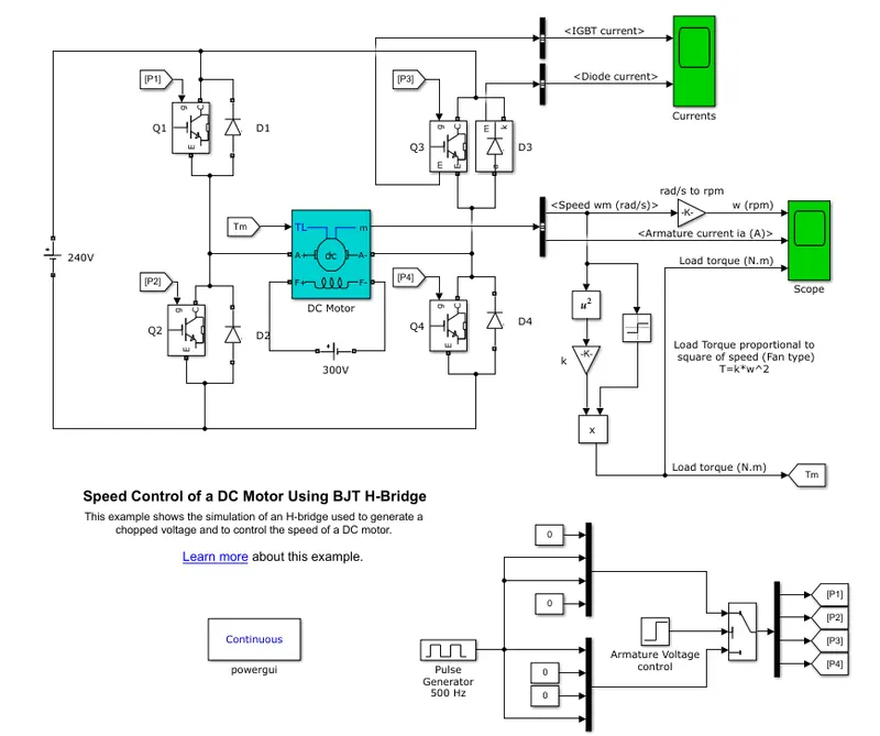
Go to the HELP documentation and type a Speed control of DC motor using BJT-H bridge.
Then click on the OPEN MODEL ,the model will open in the MATLAB command window.
RUN the model as it is and observe the graphs of the armature current.
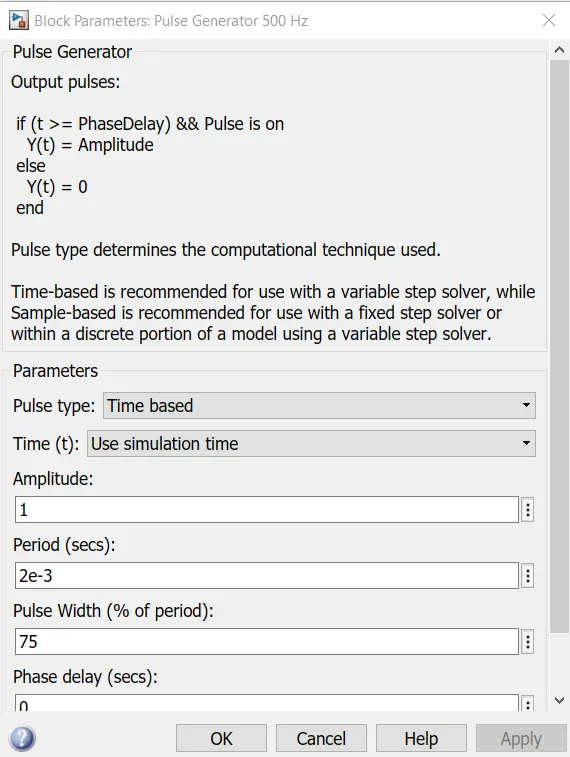
Click on the Pulse Generator block and run the model for vary the pulse width.
Scope shows for motor speed,armature current and torque.
For Pulse width 75 run the model.
Then we will get the output as below graph
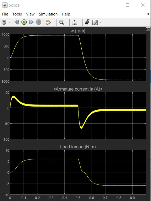
For pulse width 50 run the model.
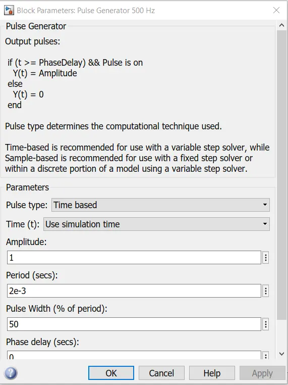
We will get the scope as below the graph.
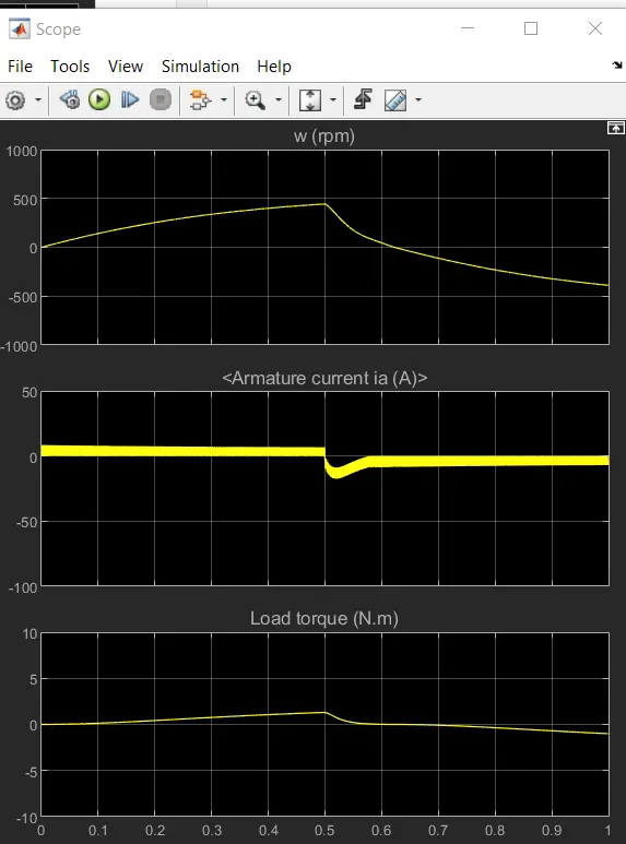
After half off the armature voltage decreases half of the simulation time.
Conclusion:As a pulse width decreases the steap value of the armature current decreases.
Comparision
1. In four Quadrant chopper DC drive distributes required current supply for each sector of four quadrants like forward motoring,forward regenerative braking,reverse motoring and reverse regenerative braking. where H-bridge supplies an irregular current for each sector that causes a voltage fluctuations in the armature current.In this it performs a forward motoring and reverse motoring.
2.In the industrial applications this H-bridge because in this industrial level four quadrants operations are required for to handle more power,since these circuits are used.
3.The efficiency in the Chopper DC-DC motor is high than the H-bridge circuit.
4.The maintainance is very less H-bridge than the Chopper DC-DC motor ,since the chopper has high switching frequency than the H-bridge.
5.The regenerative is possible in Chopper DC-DC mtor is possible but it is not happening in H-bridge circuit.
6.H-bridge circuits are used in Robotics technology,but four quadrant applications are used in other as engine test loading system.
7.H-bridge circuit can be used as a motor driver circuit it can be replaced with a less space but four quadrant operation is lightweight in nature.
8.In H-bridge ,if we want to change to the opposite direction then we want to change the polarity to control the motor but in the chopper we need to interrupt one signal under the control of another.
Conclusion:
Detailed explanation given for the four quadrant operations and their simulink result of BJT-Hbridge.
2. Develop a 2-quadrant chopper using simulink & explain the working of the same with the relevant results. (Refer to article - Multiquadrant operation of motor )
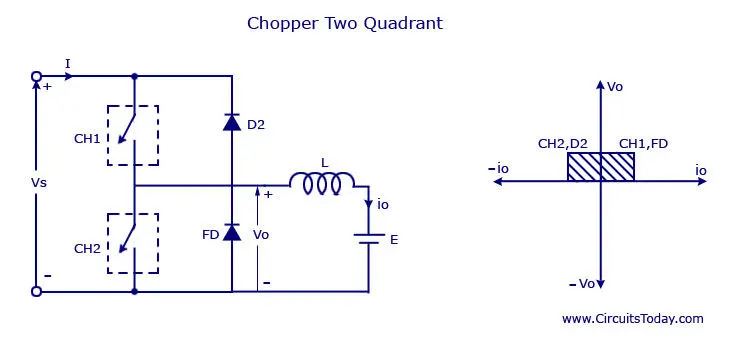
Two quadrant chopper is also called as type C chopper.Type C chopper is obtained by connecting type A and type B choppers in parallel.We will always get a positive output voltage Vo as the free wheeling diode FD is present across the load.When the chopper is ON the free wheeling diode starts conducting and the output voltage Vo will be equal to Vs.The direction of the load current Io will be reversed.The current Io will be flowing towards the source and it will be positive regardless the chopper is ON or the FD conducts.The load current will be negative if the chopper is on or the diode D2 conducts.We can say the chopper and FD operate together as type A in the first quadrant.In the second quadrant the chopper and D2 will operate together as type B chopper.
The average voltage will be positive always but the average load current might be positive or negative.The power flow may be in the first quadrant operation i.e from source to load or from load to source i.e in the second quadrant operation.The two choppers should not be on simultaneously as the combined action may cause a short circuit in the supply line.For regenerative braking and motoring these type of chopper configuration is used.
Two quadrant chopper model using Simulink.
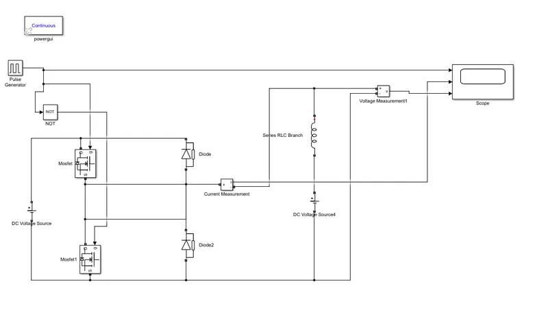
This simulink model is prepared by adding the DC volltage source,voltage measurement,current measurement,MOSFETs,diodes,pulse generator,series RLC branch,scope.
To do the simulation we have to add a powergui continuous block.In the Mosfets and diodes we have to disable the measurement ports and click ok.
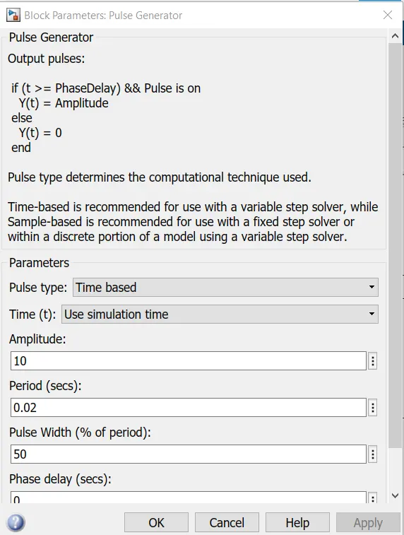
The main DC voltage source,set the amplitude as 24V.
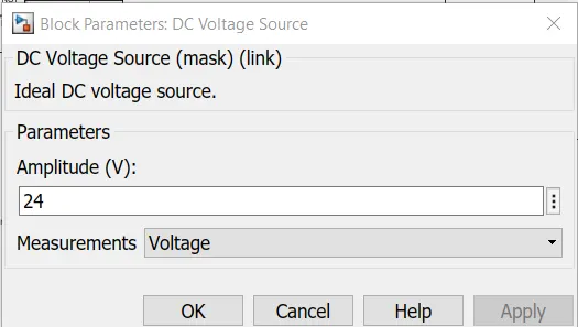
In the series with the RLC branch select a L inductance and set the voltage DC as 12V.
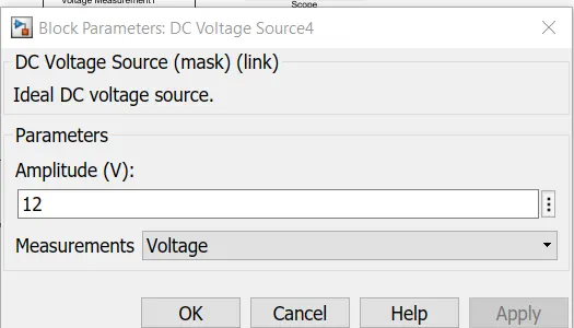
In the pulse generator block as specified in the block parameter below ,since it is used to create a gate pulse.Not block in which rectangular icon is used in the two MOSFET will not get closed at the same time otherwise short circuit will occur.
By using this NOT gate when one mosfet is on the other mosfet will off or 2nd mosfet is on then the 1st mosfet is off.
Scope Result:
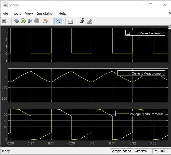
From the graph,the pulse amplitude is set as 10 and the waveform is also we can see 10.
Conclusion:
The current waveform the current increases and decreases,when it is positive and negative.
the voltage waveform is always maximum and it will not be always negative it will not exceed 0V
in the negative direction and more it will be in the positive direction.
3. Explain in a brief about operation of BLDC motor.
BLDC Motor:
BrushlessDC motors, knownly call it as electronically commutated motors.It is a permanent magnet synchronous electric motor which is driven by Direct current and it has controlled commutation system,where commutation is the process of producing rotational torque in the motor by changing the phase current through it appropriate times instead of mechanicall commutation system.It also call as trapezoidal permanent magnet motors.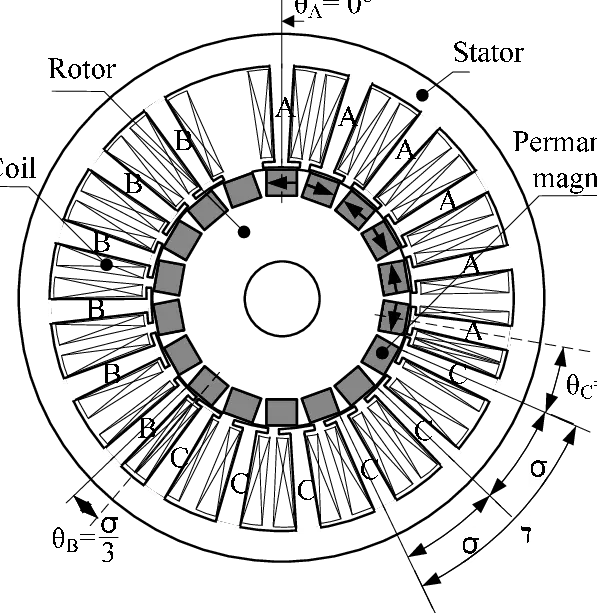
In the BLDC motor,the brushes have the mechanical contact with commutator on the rotor side this forms the electrical path between DC electric source and rotor armature windings this motor forms a electrical commutation with permanent magnet rotor and stator with a sequence of coil.In this BLDC motor,permanent magnet rotates and current carrying conductors are fixed.
The armature of coils are switched electronically by transistor or SCR at the correct rotor position in such a way that armature field in space quadrature with rotor field poles.therefore rotator rotates.
Hall sensors are also called as rotary encoders.It used to sense the position of the rotor and are fixed around the stator.It confirms that whether it is fixed correctly or not from this feed back iot helps to determine when the armature current should be on.
This arrangement eliminates the commutator and brushes in the brushes dc motor and hence more reliable and less noisy operation is acheived.Due to the absence of brushes since BLDC motors are capable of running at a high speeds.This BLDC motor achieves 85-90% but the brushed DC motor efficiency is 75-80%.So there is a wide varieties of BLDC motors are available from small amount of power to horse power,large power ranges.
In this motor,the permanent magnet attach to the rotor,the current carrying conductors are located on the stator.This commutation converts from electrical energy to mechanical energy.
In a BLDC motor mechanical commutator is replaced with electric switch circuits when compared to brushed DC motor.BLDC motor is a type of synchronous motor in the sense that the magnetic field generated by the stator and the rotor revolves of same frequency.
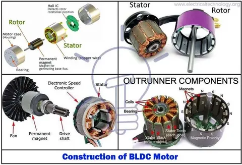
BLDC motor does not have any current carrying commutators.the field inside a brushless motor is switched through an amplifier which is triggered by the commutating device like an optical encoder.
It is configured with the different physical parameters depends on their stator windings where it has single phase,two phase or three phase.Typically use BLDC three phase motors with permanent magnet rotor.
The BLDC motor has vary with outrunner and inrunner style.
Outrunner:The field magnet is a drum rotor which rotates around the stator,this type of application is used in high torque and less RPM required.
Inrunner:The stator is a fixed drum in which the field magnet rotates,this type of application is used in less torque and high RPM required.
STATOR:
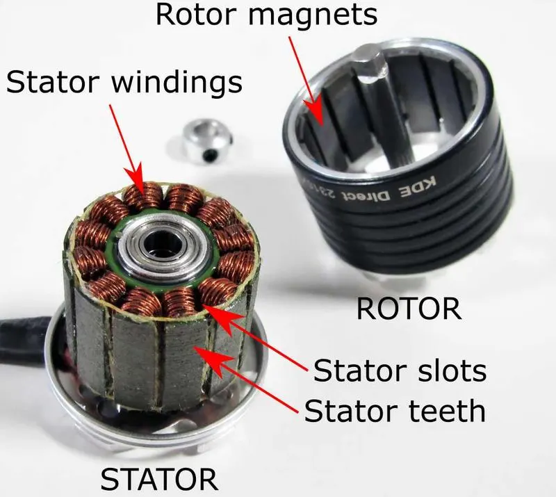
It is made up of stacked steel laminations to carry the windings.These windings are in the form of slots which are axialy cut along the inner periphery of the stator.these windings can be arranged in the form of star or delta.
The formation of the qwinding is connected with the numerous coils,these coils are placed in the slots,inorder to form the poles,these windings distributed equally over the stator periphery.
This stator must be choosen with the correct rating of the voltage depending on the power supply capacity.These motors preferred less voltage i.e 48v for robotics,automative and small actuators.
ROTOR:
The motor has incorporated permanent magnet with the rotor.It has 2 to 8 pairs of poles in the south and north direction.To achieve maximum torque in the motor the flux density of the material should be high.Rare earth alloy is typically used for new designs.This rotor can be configured with different core configuration such as the circular core with permanent magnet on the periphery,circular core with permanent magnets ..
The ferrite magnets have low flux density and they are inexpensive.A proper magnetic material of the rotor is needed to produce required magnetic field density.
HALL SENSOR:
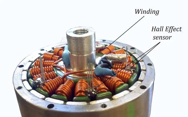
It provides the information to the synchronous stator armature excitation with rotor position.Since the commutation of BLDC motor is controlled electronically,the stator windings shoulbe energised in sequence inoder to rotate the motor.Before energising the stator windings acknowledgement of rotor position is necessary.This hall effect sensor placed inside the stator sensors position.
Three hall sensors embedded into the stator in all the BLDC motors.Each sensors generates low and high signals whenever the rotor poles pass near to it.The exact commutation sequence to the stator winding is can be determined by the three hall sensors.
Working of BLDC motor:
The BLDC motor has internal shaft position feedback where as in brushed DC motor,feedback is implemented using a mechanical commutator and brushes but in BLDC multiple feedback sensors are there.The most commonly used sensors are hall and optical encoders.These hall sensors work on the hall effect principles when the current carrying conductor is exposed to the magnetic field ,charge carries experience a force based on the voltage developed across the two sides of conductor.
If the direction of the magnetic field is reversed then the voltage developed ialso reversed.Three hall sensors embedded into the stator in all the BLDC motors.Each sensors generates low and high signals whenever the rotor poles pass near to it.The exact commutation sequence to the stator winding is can be determined by the three hall sensors,it also determines the position of the shaft.
In a commutation system,one that is based on the position of the motor identified using feedback sensors,two of the three electrical are energized at a time as shown in the below figure.
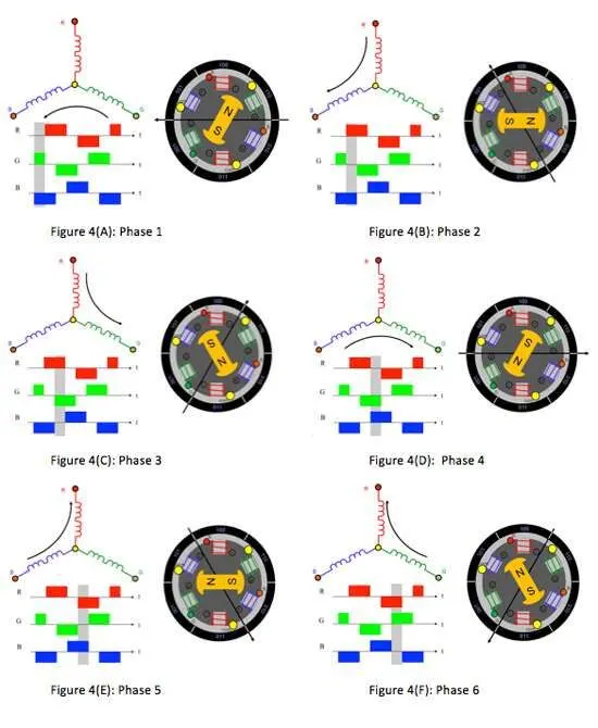
In the figure A "001"winding in the green which is energised as north pole and "010"winding in the blue colour in the south pole.Due to this excitation south pole of thr rotor aligns with the green winding and the north pole aligns with red winding as "100".In order to move the rotor,the red and blue windings are energized in the direction as shown in the figure B.this causes red winding to become the north pole and blue winding to become the south pole.THis shifting of the magnetic field in the stator produces the torque because the development of repulsioni.e red winding north -north alignment attracts the force of blue winding north -south alignment which moves the rotor in the clockwise direction.
This torque is maximum when the rotor starts to move ,but it reduces as the fields align to each other .To build up this rotation,the magnetic field generated by the stator should keep switching.To catchup this field by the stator ,the rotor keeps rotating.Since the both stator and the rotor magnetic fielkd will be at same frequency.Therefore they call it as synchronous motors.
The switching of the stator to build up the rotation is called commutation,3 phase windings,6 steps 6 commutation unique combination in which th emotor windings will get energized.
Advantages :
*Less maintainance due to absence of brushes.
*Higher speed range and lower electrical noise generation.
*Higher efficiency and high output power.
*Less electromagnetic interference.
Disadvantages:
*These motors are costly.
*Requires complex drive circuitry.
*Need of addtional sensors.
*Electronic motor controll switch is expensive.
Applications:
It will be used in the industrial applications i.e fields of industrial control,automation systems,health care equipments,etc...
Conclusion:
We have seen the operation of BLDC motor.