Week-7 Challenge: DC Motor Control
Study 1A :
Objective:Explaining a MATLAB demo model named ‘Speed control of a DC motor using BJT H-bridge’.
H Bridge is a simple electronic circuit which enables us to apply voltage to load in either direction. It is commonly used in robotics application to control DC Motors. By using H Bridge we can run DC Motor in clockwise or anticlockwise directions. This circuit is also used to produce alternating waveforms in inverters.
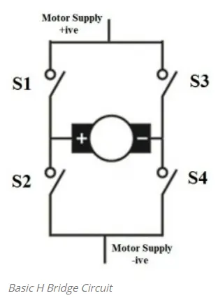
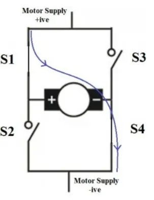
When switches S1 and S4 are switched on, motor runs in clockwise direction.
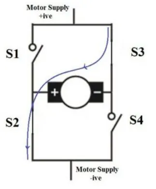
When S2 and S3 are switched on, motor runs in anticlockwise direction.
In actual practice these switches are replaced by transistors.
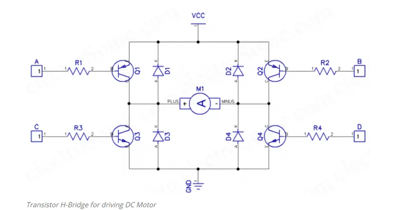
In this circuit all transistor are wired as a switches. An NPN transistor (Q3 and Q4) will be ON when we give HIGH to it and a PNP transistor (Q1 and Q2) will be ON when we give LOW to it. So when (A = LOW, B = HIGH, C = LOW, D = HIGH), transistors Q1 & Q4 will be ON and Q2 & Q3 will be OFF, so the motor rotates in clockwise direction. Similarly when (A = HIGH, B = LOW, C = HIGH, D = LOW), transistors Q2 & Q3 will be ON and transistor Q1 & Q4 will be OFF, thus the motor rotates in anticlockwise direction. (D1 ~ D4) is uses as freewheeling diode as it is a fast switching diode. It avoids problems due to negative voltage produced by the back emf the dc motor. Resistors R1 – R4 are used to limit the input current of transistors and are designed in such a way that transistor will work as a switch. Transistor should be chosen according to the current requirements of the DC Motor.
In order to vary the speed of the DC motor we have to change the voltage applied to the DC motor.This could be achieved with the help of the pulse width modulation.
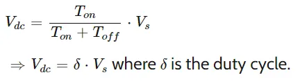
Pulse width modulation means varying the width(duty) of pulse.Width means ON time Ton of pulse. The average output voltage (Vdc or Vavg)is given by equation.
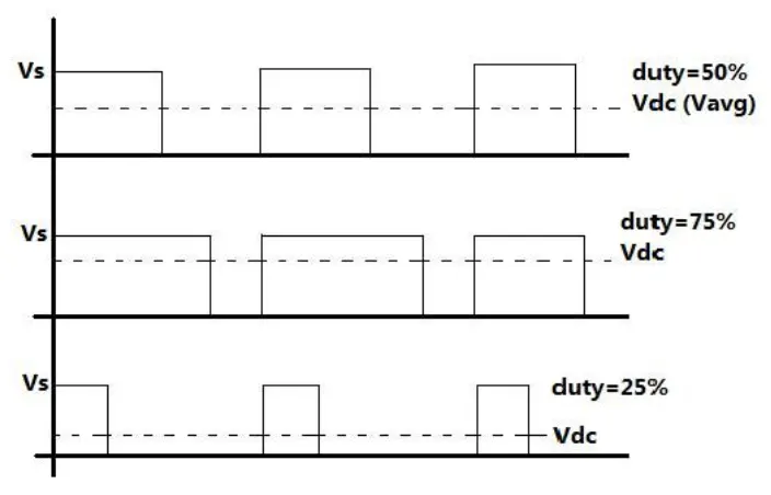
The voltage directly depends upon Ton. A shown in above fig if duty is 50% the average output Vdc is exactly the half of Vs. If duty is increased to 75%, Vdc also increases to 3/th of Vs and if duty is decreased to 25%, Vdc reduces to 1/4th of Vs.
Thus as pulse width varies the average output voltage varies.so we have to apply PWM to DC motor to vary its speed.
‘Speed control of a DC motor using BJT H-bridge:
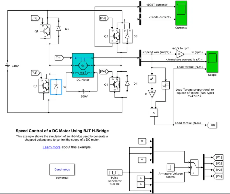
The Bipolar Junction Transistor (BJT) when used for power switching applications, operates as an IGBT. When it is conducting (BJT operating in the saturated region), a forward voltage Vf is developed between collector and emitter (in the range of 1 V). Therefore, the IGBT block can be used to model the BJT device.
The IGBT block does not simulate the gate current controlling the BJT or IGBT. The switch is controlled by a Simulink® signal (1/0). The DC motor uses the preset model (5 HP 24V 1750 rpm). It simulates a fan type load (where Load torque is proportional to square of speed). The armature mean voltage can be varied from 0 to 240 V when the duty cycle (specified in the Pulse Generator block) is varied from 0 to 100%.
The H-bridge consists of four BJT/Diode pairs (BJT simulated by IGBT models). Two transistors are switched simultaneously: Q1 and Q4 or Q2 and Q3. When Q1 and Q4 are fired, a positive voltage is applied to the motor and diodes D2-D3 operate as free-wheeling diodes when Q1 and Q4 are switched off. When Q2 and Q3 are fired, a negative voltage is applied to the motor and diodes D1-D4 operate as free-wheeling diodes when Q2 and Q3 are switched off.
Study 1B:Comment on the armature current shoot-up from the scope results.
The motor starts in the positive direction with a duty cycle of 75% (mean DC voltage of 180V). At t= 0.5 sec., the armature voltage is suddenly reversed and the motor runs in the negative direction.
'Scope' shows motor speed, armature current and load torque and 'Currents' shows currents flowing in BJT Q3 and diode D3.
From the scope result we can see that there is sudden spike increase in current at 0 sec and at 0.5 sec also .Transition from positive to negative direction of rotation we observe a high surge in current this is because of transient switching occuring in the circuit.

As there is already current flowing in the circuit and on changing of switches after 0.5sec, the current in the circuit add to the changed direction of current and we observe a surge in the current , the surge in the current can be reduced by reducing the duty cycle
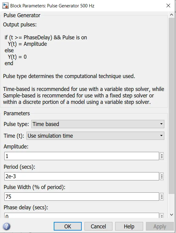
In the above results, the duty cycle selected as 75%
case 2:
Duty cycle reduced to 50%
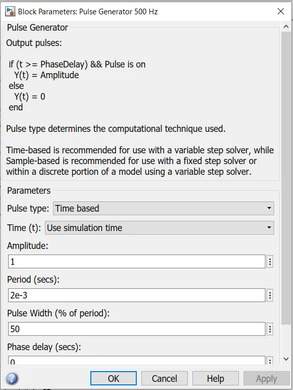
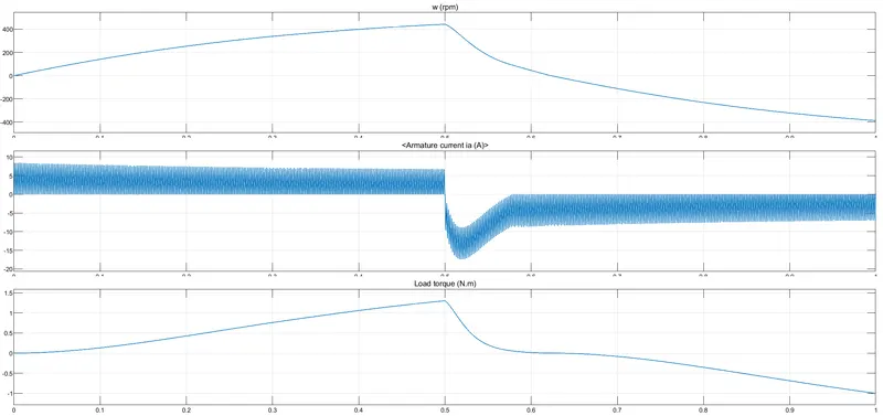
When pulse width decreases , the voltage applied across the DC motor decreases and the armture current finally decreases.
Study 1C:Refer to the help section of ‘The Four-Quadrant Chopper DC Drive (DC7) block’. Compare it with the H-bridge model.
The Four-Quadrant Chopper DC Drive (DC7) block
- The Four-Quadrant Chopper DC Drive (DC7) block represents a four-quadrant, DC-supplied, chopper (or DC-DC PWM converter) drive for DC motors.
- This drive features closed-loop speed control with four-quadrant operation. The speed control loop outputs the reference armature current of the machine.
- Using a PI current controller, the chopper duty cycle corresponding to the commanded armature current is derived. This duty cycle is then compared with a sawtooth carrier signal to obtain the required PWM signals for the chopper.
- The main advantage of this drive, compared with other DC drives, is that it can operate in all four quadrants (forward motoring, reverse regeneration, reverse motoring, and forward regeneration).
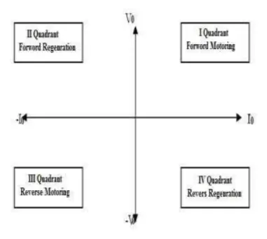
- In addition, due to the use of high switching frequency DC-DC converters, a lower armature current ripple (compared with thyristor-based DC drives) is obtained.
- However, four switching devices are required, which increases thecomplexity of the drive system.
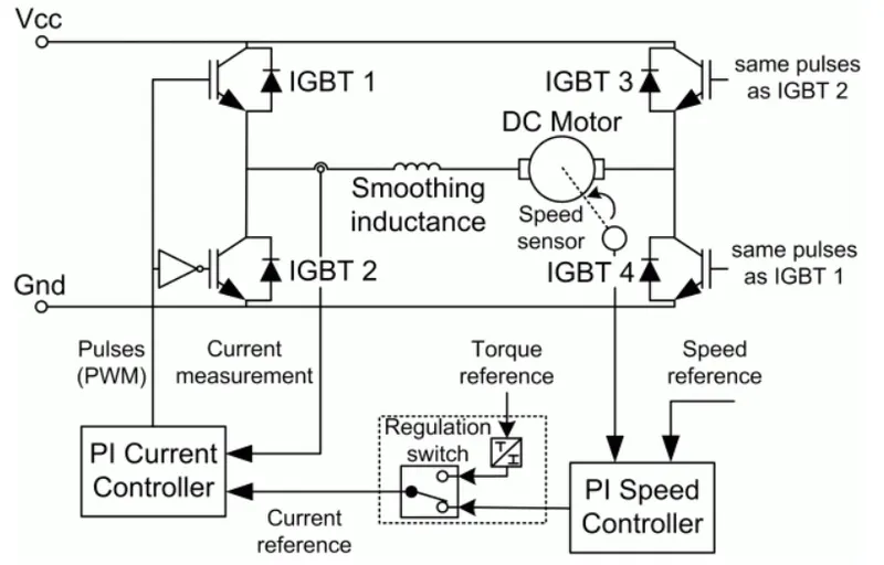
The Four-Quadrant Chopper DC Drive block uses these blocks from the Electric Drives/Fundamental Drive Blocks library:
-
Speed Controller (DC)
-
Regulation Switch
-
Current Controller (DC)
-
Chopper
The machine is separately excited with a constant DC field voltage source. There is thus no field voltage control. By default, the field current is set to its steady-state value when a simulation is started.
The armature voltage is provided by an IGBT converter controlled by two PI regulators. The converter is fed by a constant DC voltage source. Armature current oscillations are reduced by a smoothing inductance connected in series with the armature circuit.
comparison of 4- quadrant chopper and BJT H bridge:
| 4-Quadrant chopper | BJT H Bridge |
| it can operate in all four quadrants (forward motoring, reverse regeneration, reverse motoring, and forward regeneration) | It can operate only in 2modes(Forward,Reverse) |
| Regenerative braking is possible | Regenerative braking is not possible |
| 2 PI regulator (speed regulator and current regulator) is used | No PI regulator is used. |
| Lower armature current ripple due to high switching frequency of DC-DC converters. | High armature current ripple |
| more complex | less complex |
| Discrete and simulation time is less. | simulation is continous and simulation time is more. |
| widely used in automobiles | Widely used in Robotics |
| It provides better efficiency and high energy storage | It provides less efficiency compared to quadrant chopper |
Study 2:
Objective: Developing a 2-quadrant chopper using simulink
chopper:
- The chopper converts the fixed DC voltage to variable DC voltage.
- Self-commutated devices (directly on or off devices via gate) like MOSFET, IGBT, power transistors, GTO and IGCT are used for making choppers because they can be commutated by low power control signal and do not need commutation circuit.
- The chopper was operated at high frequency due to which it upgrade the motor performances by decreasing the ripple and removing the discontinuous conduction.
- The most important feature of chopper control is that the regenerative braking is carried out at very low generating speed when the drive is fed from a fixed voltage to low DC voltage.
This study is carried for 2-quadrant chopper where 2 MOSFET's are used
Case 1: Chopper ON/OFF condition
- When the Chopper CH1 is ON the current flows from source to Load and the energy stores in the inductor. In this case the Output voltage Vo is equal to Vs.
- The direction of current flow is from source to Load as shown in the below diagram it is considered as positive.
- When the choppper CH1 is OFF,the fee wheeling diode FD comes into the circuit as it gets forward biased and hence shorts the load.In this case the output voltage Vo become zero.
- However the current io continues to flow from FD and L in the same direction as shown below.
Case 2: Chopper ON/OFF condition
- When the chopper CH2 is ON the current flows from Load to Source.
- The direction of current will be opposite to that shown in the circuit diagram and it is considered as negative.
- The output voltage Vo is zero.
- When the Chopper CH2 is OFF ,Diode D2 gets forward biased and hence the current flows from source to Load.
- The output voltae is Vs , as the load is connected to the source through D2 during OFF condition of chopper CH2.
- The load current is always negative in this case.
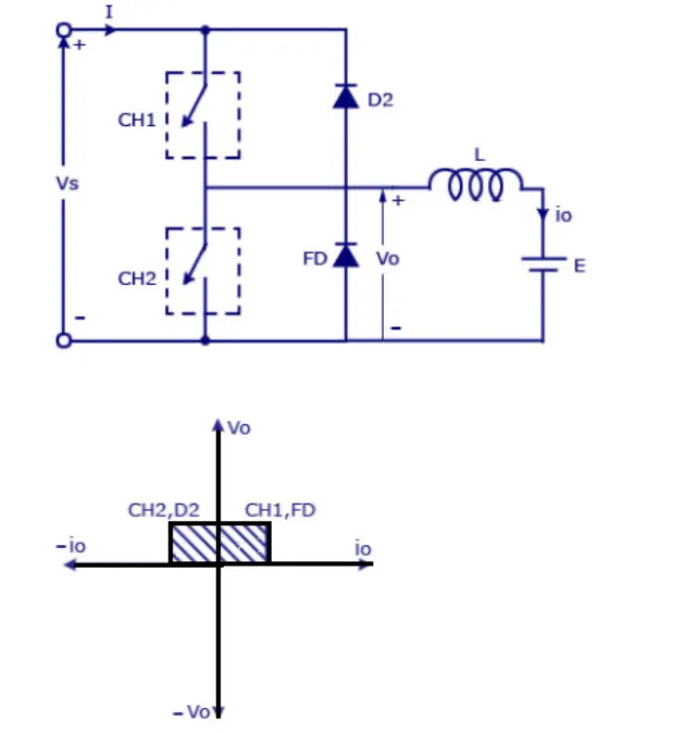
In this type of chopper, the average voltage will be aways positive but the average current might be positive or negative .
The 2 switches CH1 & CH2 should not bbe turned on simultaneously as the combined action may cause a short circuit in the supply lines.
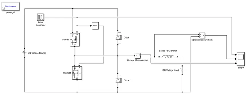
The simulink model is developed from a Circuit diagram as shown above.
Procedure:
- Mosfet & diode blocks: Let us take 2 Mosfet and diode blocks and are connected as shown in the circuit diagram
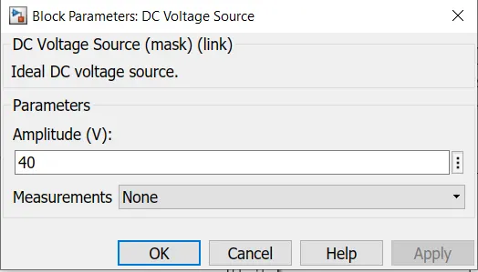
- DC Voltage source/Load:The DC voltage is connected to the both Mosfet and diode as shown above correspoding the positive and negative.
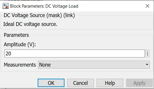
- Series RLC branch:The series RLC branch block is taken and branch type is change to L.This block is a inductor L which stores the energy and works as a load and this block is connected to the Load of the DC voltage.
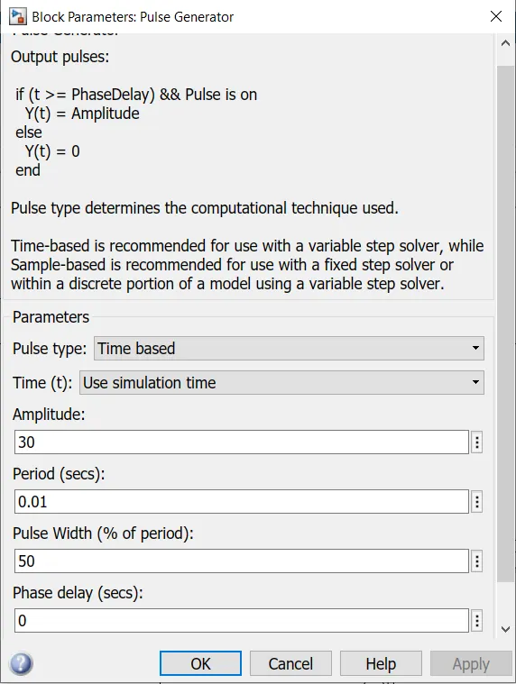
- Pulse generator:This block is used to create a gate pulse
- NOT: This block is used to prevent misfiring of Mosfet's so that they do not conduct at the same time which results in the shot circuit otherwise.
- Current Measurement:This block is used to check the current waveform
- Voltage measurement:This is used to check the voltage waveform
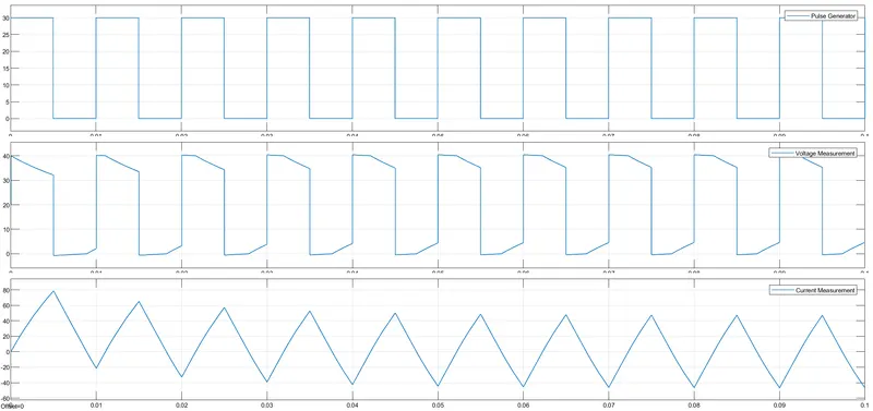
- Scope:This block is used to study the 3 results of pulse generator, voltage measurement and current measurement.
- Powergui: This block is used for the smilution and should be located at the highest level of the diagram where Simscape Electrical Specialized Power Systems blocks are found.
Results:
From the scope we can observe that the voltage is not going below zero. The minimum value of the voltage is zero and maximum is positive.
The current waveform in the 3rd graph shows that the current increases initially and deacreses , as discussed the current may positive as well as negative.
Study 3:
Objective:Operation of BLDC motor.
BLDC stands for Brushless DC motor.A brushless DC electric motor (BLDC motor or BL motor), also known as electronically commutated motor (ECM or EC motor) and synchronous DC motors, are synchronous motors powered by direct current (DC) electricity
Brushless motors are not self-commutating, and hence are more complicated to control.
Types of BLDC:
Outrunner: This type of motor spins its outer shell around its windings, much like motors found in ordinary CD-ROM computer drives. The permanent magnets spin around the static rotor.
Inrunner: The permanent magnets spin inside the static rotor.
Semiconductor control is used for controlling the stator current in such a way that maximum torque is obtained at a given speed.
Construction of BLDC motor :
Stator has 3 phase winding while rotor is in the form of permanent magnet.
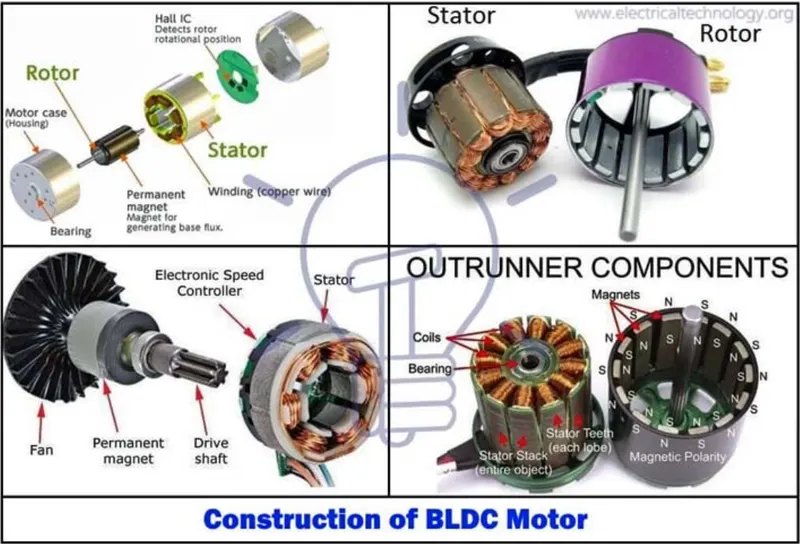
- BLDC motor also consist of rotor positon sensors which produce electrical signals that indicate the current position of the rotor.
- BLDC stator winding is driven from an electronic drive which is 3-phase inverter.
- speed of BLDC can be controlled by controlling its stator voltage which can be achieve by controlling the DC input voltage of the inverter.
Use of BLDC Motor:
It can operate at speeds above 10,000 rpm in both loaded and unloaded conditions.
BLDC motors have the highest running torque per cubic inch of any DC motor.
BLDC motors do not have brushes, meaning they are more reliable and have life expectancies of over 10,000 hours. This results in fewer instances of replacement or repair and less overall down time.
Inner rotor Brushless DC motors have low rotor inertia, allowing them to accelerate, decelerate, and reverse direction quickly.
Operation of BLDC:
A permanent Magnet AC motor, which has a trapezoidal back emf, is referred to as brushless DC motor (BLDC). The BLDC drive system is based on the feedback of rotor system at fixed points for commutation of the phase currents.
The BLDC motor requires quasi-rectangle shaped currents fed into the machine. Alternatively, the voltage may be applied to the motor every 120°, with current limit to hold the current within motor capabilities. Because the phase currents are excited in synchronism with the constant part of the back emf, constant torque is generated. The electromagnetic torque of the BLDC motor is related to the product of phase, back emf and current. The back emf in each phase are trapezoidal in shape and are displaced by 120 electrical degree with respect to each other in 3 phase machine. A rectangle current pulse is injected into each phase so that current coincides with the back emf waveform; hence the motor develops an almost constant toque.
Sensors:
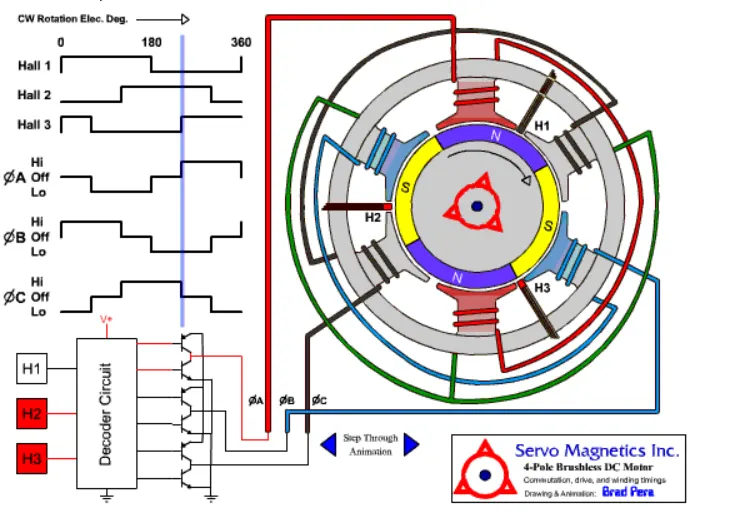
- Hall Effect sensor provides the portion of information needed to synchronize the motor excitation with rotor position in order to produce constant torque.
- It detects the change in magnetic field.
- The rotor magnets are used as triggers to the Hall Sensor.
- A signal conditioning circuit integrated within the Hall switch provides a TTL-compatible pulse with sharp edges.
- Three Hall Sensors placed 120° apart, are mounted on the stator frame.
- The Hall Sensor digital signals are used to sense the rotor
Baisc operating principle:
- Stator has 3 phase windings
- When energize phase A , stator poles S & N are created.
- Stator poles repels rotor S pole & attract rotor N pole.
- Clockwise torque is produced.
- The magnitude of this torque is given by
T = Kϕs ϕR sinθ
Where k = constant,
ϕs = Stator Field flux
ϕR = Rotor field flux
θ = torque angle
This shows that the torque is sinusoidally proportinal to the torque angle θ.
Magnitude of the stator file flux is proportional to stator current I1 and the rotor field is constant
T= k1 I1 sinθ
The stator phase are energized in the sequence A,B,C so as to have clockwise rotation of the machine.
Applications:
- Computer periphereal equipments
- Instrumentation and control systems
- Electric power steering
- Air conditioners
- Bio medical instrumentation
- In Aerospace