Week -2
1) Objetcive:The main objective of this model is to create a doorbell using solenoid block where the switch is closed for 2seconds and then release . And also to observe the position of plunger.
The basic components to create this model:
- Battery
- Switch
- Solenoid
- A bell with a plunger
Procedure:
- Solenoid block is used to do doorbell model. This block is taken from the library browser.
- A solenoid is a device comprised of a coil of wire, the housing and a moveable plunger (armature). When an electrical current is introduced, a magnetic field forms around the coil which draws the plunger in. More simply, a solenoid converts electrical energy into mechanical work.
- Now we take Battery from library browser.
- we connect Battery and solenoid with the positive & negative terminals.
- Switch is taken and is connected between the battery and solenoid.
- Now to operate switch we must provide a PS input signal in the switch block.The provided PS signal must be greater than the threshold value of the switch ,for the switch to close or else it will open.
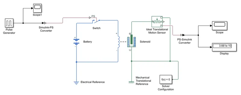
- In our case the threshold value of switch is 0.5 and physical signal is 1 which is greater than threshold so switch is closed.
- The Switch,Battery,Solenoid is connected to Electrical reference. Electrical reference represents the earthing of the circuit.This Electrical reference is connected to the neagtive terminal of the battery.
- Now Ideal translational motion sensor is taken and 'R' in the Ideal translational motion sensor is connected to 'R' of solenoid which senses the position of the plunger.
- In the Solenoid 'R' & 'C' are two variables which represent the plunger and fixed point.
- As 'C' in the solenoid and ideal translational motion sensor are fixed points so these 2 points are connected to Mechanical reference.
- Now V & P represents the velocity and plunger output but we need only position of the plunger so we connect PS-Simulink converter to 'P'.
- After connecting the output position of plunger to PS-Simulink converter ,it is then connected to 'Scope Block' where the graph is generated for PS-Simulink converter for output position of plunger from Ideal translational motion sensor.
- To provide the physical signal for operating the switch,we use 'Pulse Generator block'.
- Pulse Generator Block generates continouse square plus.
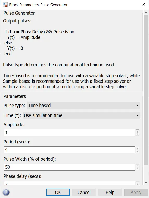
- As mentioned in the block table pluse width is given as 50 , periods as 4 ,amplitude is 1 by default,phase delay as 2 seconds.
- Now Pulse Generator Block is connected to 'Scope Block' to check the pulse generation.
- From the below graph we can see that Initially the Pulse will at zero at 2 seconds and the pulse width will be half of the period and amplitide is at 1 and again the pulse is zero at 4seconds and it remains zero for next 2seconds and it completed the period of 4seconds.
- From the graph we can observe that the pulse will take 4seconds of time period in which 2 seconds will be at zero and next 2seconds will be at amplitude 1.
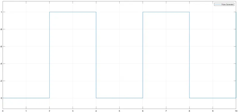
- As discussed the pulse starting at 2sec and it ends at 6 seconds with a time period of 2seconds.
- So When the amplitude is 1 the switch is closed and when it is zero the switch is open.
- Our objective is to observe the physical movement of the plunger when is switch is closed for 2seconds so that we have amplitude as 1 in the pulse generator and the pulse width to be half of the period in the input of pulse generator block.
- Now the Pulse Generator is connected to 'Simulink PS converter' to convert the simulink value to physical value .
- The 'simulink PS converter' is connected to Switch to get the inputs.
- Now the 'Solver configuration block' is connected as shown.
- Each physical network represented by a connected Simscape block diagram requires solver settings information for simulation. The Solver Configuration block specifies the solver parameters that your model needs before you can begin simulation.
- Once the solver is connected and Display also connected to the 'PS Simulink converter'to get the ouput result.
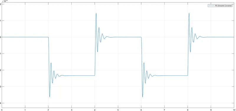
- Now we can click run to get the output and double click on the 'scope block' at Ideal translational motion sensor' to get the position of the plunger.
- From the below graph we can the see the position of the plunger.
2)
Objetcive:The main objective is to create a simulink model by using a thermistor to sense the temperature of a heater & turn ON the fan above 25 °C
Temperature source: 20 °C from 0 to 10 seconds, 27 °C from 10 to 30 seconds, 23 °C from 30 to 50 seconds
Procedure:
- Firstly,We use thermistor for heating purpose and we take this thermistor from the library browser.
- This thermistor is connected to Temperature controlled source and battery as it ontains thermal and electrical port.
- A port of the thermistor is connected to temperature controlled source and T port is connected to the positive terminal of the battery.
- This block(controlled temperature source) represents an ideal energy source in a thermal network that can maintain a controlled temperature difference regardless of the heat flow rate. The temperature difference is set by the physical signal port S.
- The physical signal port S takes the temperature difference value with respect to time from either signal builder or repeating sequence.
- Here we have taken signal builder block to develop temperature source as mentioned in the above.
- Constructed all the temperatures(in K) as per the time seconds in the signal builder.
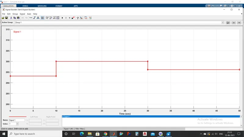
- Now the Signal builder is linked to controlled temperature source by connecting to the simulink PS converter.
- Now the negative terminal of the thermistor is connected to the positive terminal of the resistor.
- The negative terminal of the battry is connected to the electrical reference.
- A switch block is taken from the library it has 3 ports . where 2 constants are linked to operate the switch. Constant 1 represent 'ON' state and Constant 0 represents 'OFF' state of switch.
- So in our condition the switch will be ON when the temperature is above 25 °C i.e 298.15K . Switch block takes the threshold value
- We need to give the voltage value to this input.
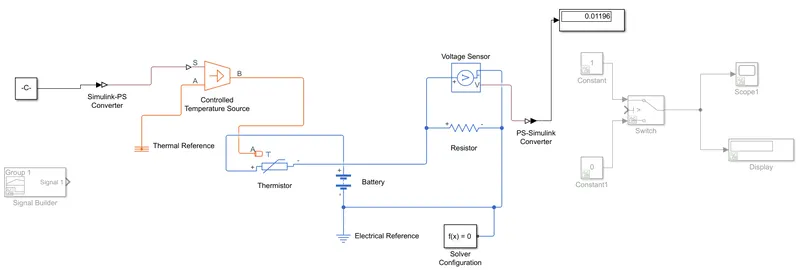
- As shown below we have to sense the voltage from the temperature . For that we link the constant value 298.15 to the controlled temperature source and and by linking voltage sensor to the resistor and output of the voltage is connected to the display by the PS simulink converter to get the output value.
- In the below model the value displayed is 0.01196.This is considered as a threshold value in the switch.
- The below model is just to find the threshold value.
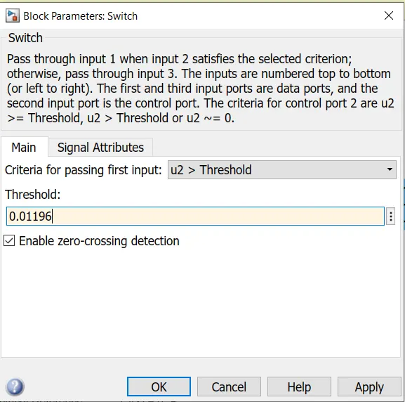
- Now after finding the threshold the constant value 298.15 can be uncommented or removed and connect the signal builder and provide the threshold value 0.01196 to the switch
- To know the switch operating condition we plot the graph using the scope and result in the display block.
- Thermal reference is provided to the 'A' port of the controlled temprature source and solver configuration is provided to run the program.
- As the system has to time limit of 50 seconds we set the stop time to 50sec and run the program.
Simulink model:
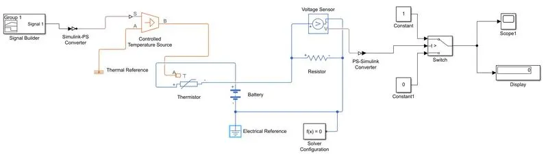
Scope:
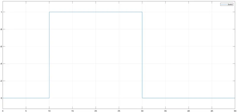
From this graph we can conclude that from 0-10sec the fan was OFF condition , and from 10-30sec it is in ON condition and 30-50sec it again OFF condition.