Week-7 Challenge: DC Motor Control
Ques 1A.
An H-bridge controller with four (4) IGBT semiconductor switches is used to control the effective voltage applied across the armature of a 5 HP 240 V DC motor with rated speed of 1750 RPM. A fixed voltage of 300 V is applied across the field windings of the DC Motor to develop a constant flux linkage between the field windings and the armature windings. The H-bridge controls the effective dc voltage applied across the armature of the DC Motor up to a maximum of 240 V. The DC Motor is used to drive a connected fan load that has a torque characteristics that varies as the square of the fan speed. Refer to Figure 1 for details.
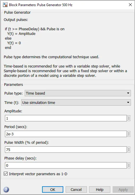
Initially, based on the Armature Voltage Control (Step Function), a 500 Hz pulse of 75% duty cycle (per Figure 4) with period of 2 ms is applied concurrently to the gates of IGBT Q1 and IGBT Q4, which causes Q1 and Q4 to be repeatably turned on for 1.5 ms and off for 0.5 ms (Note that that IGBTs Q2 and Q3 are both inactive initially). This results in an effective applied dc voltage of +180 V (0.75*240) across the armature of the DC Motor. Consequently, the DC Motor develops an electromagnetic torque that varies proportionally with the armature current. The armature current rises form 0 A and attains a steady-state value of +6.7 A with a corresponding torque of +6 Nm applied to the fan as it rotates at a constant speed of 950 RPM in the forward direction (assumed). Refer to Figure 2 for details.
At 0.5 seconds, the Armature Voltage Control (Step Function), applies the 500 Hz, 75% duty cycle pulse concurrently to the gates of IGBT Q2 and IGBT Q3, which causes Q2 and Q3 to be repeatably turned on for 1.5 ms and off for 0.5 ms (Note that that IGBTs Q1 and Q4 are both inactive at and after 0.5 seconds). This results in an effective applied dc voltage of -180 V across the armature of the DC Motor. Consequently, the armature current decreases from +6.7 A and attains a new steady-state value of -6.7 A with a corresponding torque of -6 Nm applied to the fan as it rotates at a constant speed of 950 RPM in the reverse direction (assumed). Note that as the electromagnetic torque of the DC Motor is directly proportional to the armature current, the torque applied to the fan is in the reversed direction of rotation. Refer to Figure 2 for details.
Observe in Figure 3, that armature current flows via the free-wheeling diode, D3 (and diode D2) when IGBTs Q1 and Q4 are momentarily turned off for 0.5 ms. The free-wheeling diodes are required to prevent the catastrophic failure of the IGBTs and the DC Motor. That is, in the absence of the free-wheeling diodes, a high voltage surge could develop across the armature and potentially damage the DC Motor and the components of the H-bridge.
Ques 1B.
With reference to the following equation:
`V=R*ia+L(di)/dt+Kw`
Where,
R=2.581 ohms
L=0.028 Henries
V=180V
Note that the time constant of the electrical system is much faster than that of the DC Motor mechanical system. So that at startup and a few milliseconds beyond, the speed dependent back-emf component, `Kw` can be neglected and the armature current approximated as follow:
`V=R*ia+L(di)/dt`
`ia=V/R*(1-e^(-R/Lt))`
Per the above equation, if the rotor of the DC Motor is locked or rotates at a relatively slow speed, the armature current would reach or come close to the value of `V/R`, that is 69.7 A. However, as the electromagnetic torque of the DC Motor increases, the speed of the DC Motor increases and the back-emf component `Kw` eventually becomes significant. Consequently, the rate of rise of the armature current decreases due to the rising back-emf component until a maximum armature current of 36 A is reached at 19 ms. This is the value of first armature current shoot-up value as shown in the second plot of Figure 2.
Observe in Figure 2 that the magnitude of the second (after 0.5s) armature current shoot-up (-64.5 A) is greater than that of the first. This is due to the energy required to decelerate and reverse the direction of rotation of the DC Motor. Observe that the rate of change of the motor speed is less than the rate of change of speed at startup. Consequently, the back-emf component takes longer to develop and oppose the flow of armature current. Hence the second armature shoot-up current is greater than that of the first.
Figure 1. Simulink schematic of BJT H-Bridge with 5HP DC Motor
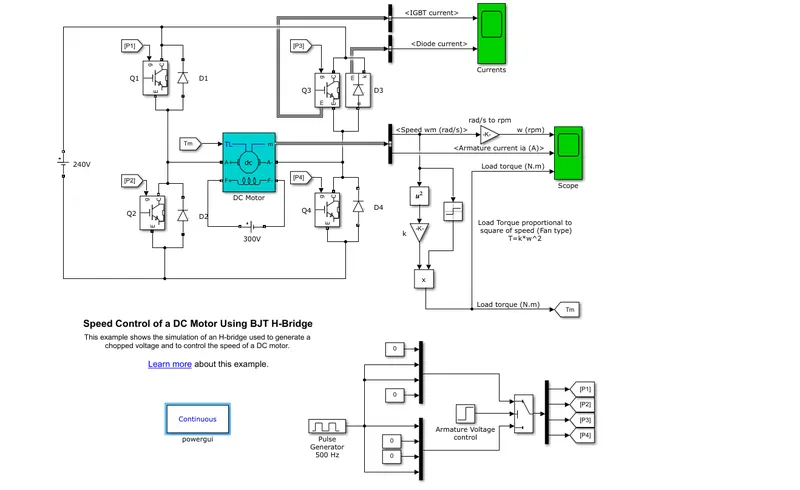
Figure 2. Plots of electrical and mechanical performance results
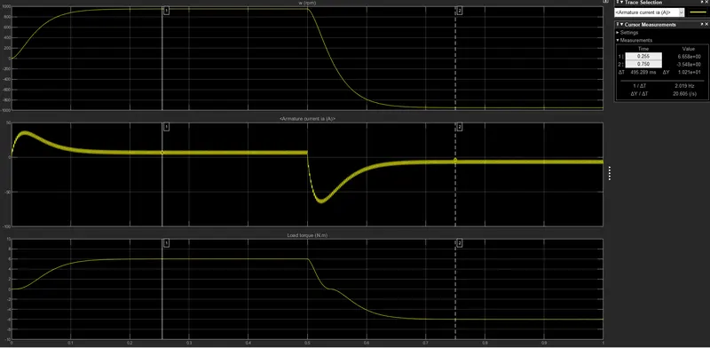
Figure 3. Plots showing IGBT and Diode currents
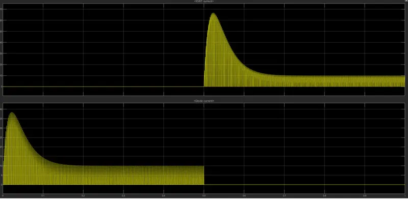
Figure 4. Duty cycle settings used in simulation
Ques 1C.
The following is a comparison between the DC7 - Four Quadrant Chopper 200 HP DC Drive shown in Figure 5, and the BJT H-bridge setup shown in Figure 1:
| DC7 - Four Quadrant Chopper 200 HP DC Drive | BJT H-bridge |
| 1) Used to drive a relatively large DC Motor. | 1) Used to drive a relatively small DC Motor |
| 2) Supplied from AC-DC converter and equipped with a braking chopper to limit the DC bus voltage during braking mode. | 2) Supplied directly from a DC voltage source and no consideration is given for voltage management during braking |
| 3) Used to control a linear load. Load torque that is directly proportional to rotational speed. | 3) Used to control a non-linear fan load. Load torque that is directly proportional to the square of the rotational speed. |
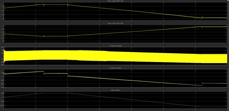
| 4) The speed of the DC Motor is regulated using speed and current feedback control. The duty cycles of the pulses to the IGBT pairs are modified by the controller to achieve regulation. Refer to Figure 6. | 4) Operated in open loop control. The operating speed is dictated by the average dc voltage to the DC Motor and the speed dependent load torque. |
| 5) The IGBTs are switched at a relatively high frequency which results in smoother armature current with no observable ripple. Refer to Figure 6. Additionally a smoothing inductance is used filter out high frequencies from the armature current. | 5) The IGBTs are operated at relatively low frequency which results in observable ripple in the armature current per second plot of Figure 2. |
Figure 5. Simulink schematic of DC7 - Four Quadrant Chopper 200 HP DC Drive
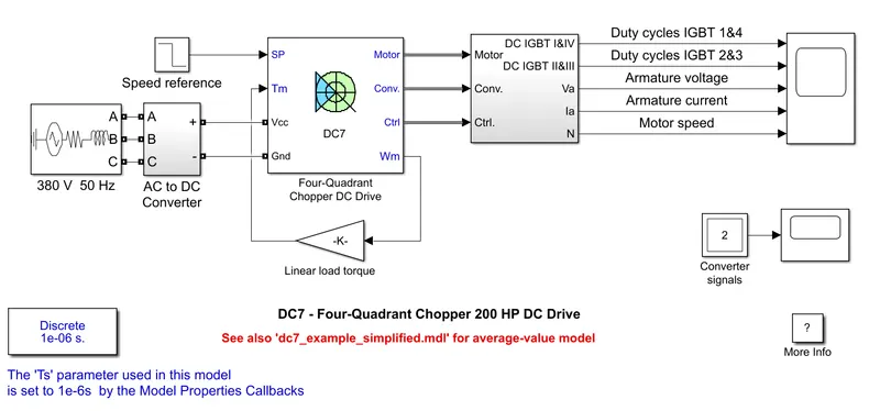
Figure 6. Selected performance plots for the results of the DC7 - Four Quadrant Chopper 200 HP DC Drive
Ques 2.
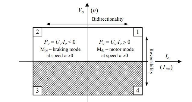
The two-quadrant chopper topology shown in Figure 7 consists of two IGBTs (Q1 & Q2) with antiparallel freewheeling diodes (D1 & D2) which forms and half bridge. The half-bridge is connected to a DC Voltage supply (Vs) and DC Motor to form a two-quadrant chopper circuit. The operating quadrants are 1 and 2. In the first and second quadrants, the voltage polarity at the DC Motor terminals remains unchanged. However, the current polarity at the DC Motor terminals is positive in the first quadrant and negative in the second quadrant. This is illustrated in Figure 10.
Pulses are sent to IGBTs Q1 & Q2 in complementary mode as illustrated in Figures 8a and 9a. The complementary pulses are generated using a NOT gate as shown in Figure 7 and the duty cycle and period of the pulses is manipulated using a Pulse Generator. The plots of the DC motor terminal voltage, armature current and speed are shown in Figures 8b & 9b. Figures 8a and 8b show the plots when the duty cycle is 25% with a period of 2 ms, whereas Figures 9a and 9b show the plots when the duty cycle is 75% also with a period of 2 ms. As expected and can be seen from the plots in Figures 8b & 9b, a lower duty cycle results in a lower average armature current in the DC Motor.
Two-Quadrant Chopper Operating Principle
Quadrant 1 Operation
Per Figure 7, when IGBT Q1 is switched on (with IGBT Q2 off), current flows through the DC Motor and grows exponentially. This current flows in the armature of the DC Motor develops a positive electromagnetic torque. During the on-time interval of T1, the supply voltage is applied across the terminals of the DC Motor. When IGBT Q1 is switched off, positive current continues to flow through the DC Motor along an alternative path through diode D2. As IGBT Q2 is now switched on, the motor's back-emf begins to act to reduce the flow of armature current. However, if the armature current remains positive when IGBT Q1 is switched on again (with IGBT Q2 off), current is drawn from the supply and the process starts over. This mode characterizes quadrant 1 operation.
Quadrant 2 Operation
When the duty cycle is set such that the average voltage at the terminals of the DC Motor is less than the developed back-emf voltage, a negative current will flow in the DC Motor. This negative current will cause a negative electromagnetic torque to develop in opposition to rotational movement. Thus the machine operates in the braking mode as a DC generator. So that energy is sent back to the supply via the chopper circuit. This energy sent back to the supply must be controlled by adding a braking resistor to prevent the catastrophic failure of the supply and bus capacitor. This is achieved by managing the chopper duty cycle such that the armature current rating is not exceeded and the energy sent back to the supply does not cause an overvoltage.
Figure 7. Simulink schematic of Two Quadrant Chopper
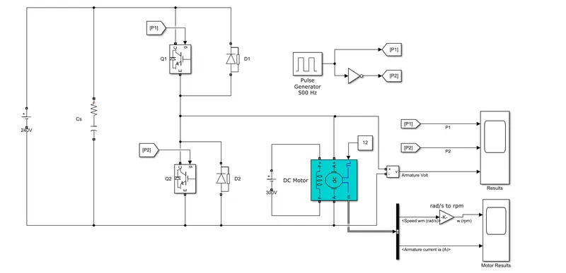
Figure 8a. Plots of gate pulses for 25% duty cycle
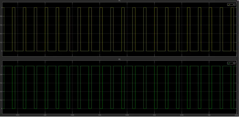
Figure 8b. Plots of motor speed, armature voltage and current for 25% duty cycle
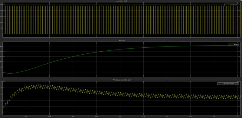
Figure 9a. Plots of gate pulses for 75% duty cycle
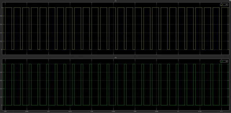
Figure 9b. Plots of motor speed, armature voltage and current for 75% duty cycle
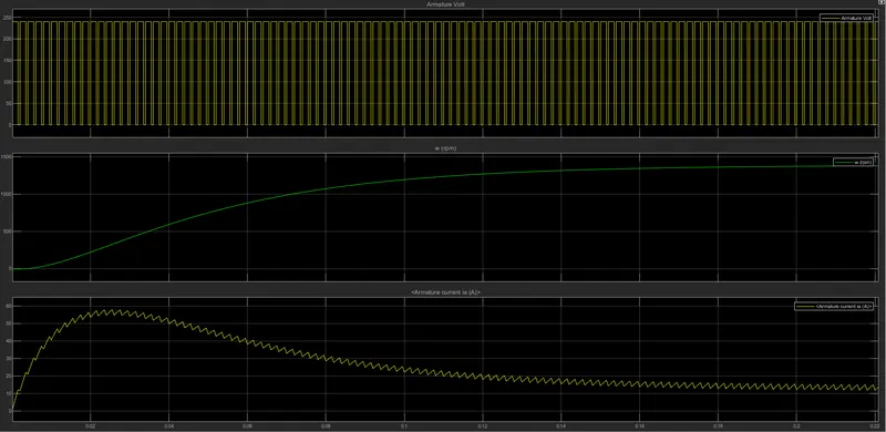
Figure 10.
Ques 3.
Description of BLDC Motor
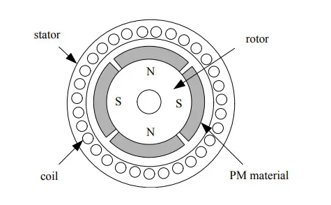
The Brushless DC Motor consists primarily of a stator and a rotor. The stator is the stationary part where a set of three-phase windings are inserted into axially cut slots. The rotor is the movable component upon which permanent magnets are mounted. As shown in Figure 11, the stator and rotor are mounted such that there is a small airgap between them. This small air-gap facilitates the interaction of the rotating magnetic field generated by the stator windings and the magnetic flux from the permanent magnet pole-pairs on the rotor. The air-gap between the stator and the rotor must be small enough to ensure efficient torque production of the BLDC Motor.
Figure 11. Cross-section of a BLDC Motor
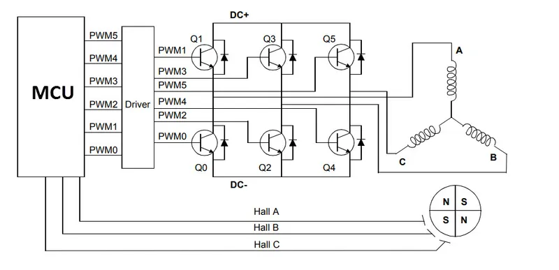
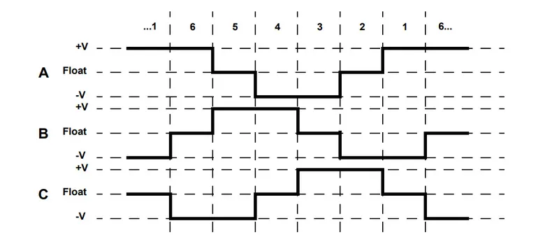
Unlike the Brushed DC Motor, the stator windings of the BLDC Motor are electronically commutated using a logic sequence that depends on the angular position of the rotor with respect to the stator. Position sensing is typically achieved via hall-effect sensors placed strategically around the stator. A digital Motor Control Unit (MCU) as shown in Figure 12, is normally used to accept the signals from a set of three hall-effect sensors. Based on the signals received from the hall-effect sensors, the MCU uses a preprogrammed logic to determine the commutation sequence for each phase of the stator windings. There are six (6) commutation events as illustrated in Figure 14.
Figure 12. Typical commutation schematic for a BLDC Motor
To understand the working principle of the BLDC Motor, consider the following setup in Figure z with three winding pairs called A, B and C. Also, a pole pair of the rotor magnet is represented by a single bar magnet. Note that current of an appropriate polarity is allowed to flow in the energized phase winding pairs to produce a magnetic field in the vicinity of the bar magnet. At any point in time, two sets of phase winding pairs are energized with the third floating or de-energized. So that a commutation sequence of six (6) discrete switching events as shown in Figure 14 is executed in one complete revolution of the bar magnet.
For example, in Sequence 1, phase winding pairs A and B are energized with opposing polarity resulting in a push and pull effect to cause clockwise rotation. That is, the bar magnet is pulled by the magnetic effect of phase A and pushed by the magnetic effect of phase B.
Furthermore, in sequence 2, phase A winding pairs are allowed to float while phase pairs B and C are energized with opposing polarity resulting in continued clockwise rotation where the magnetic effect of phase B pulls the bar magnet while the magnetic effect of C pushes the bar magnet.
Figure 13. Simplified illustration of BLDC Motor
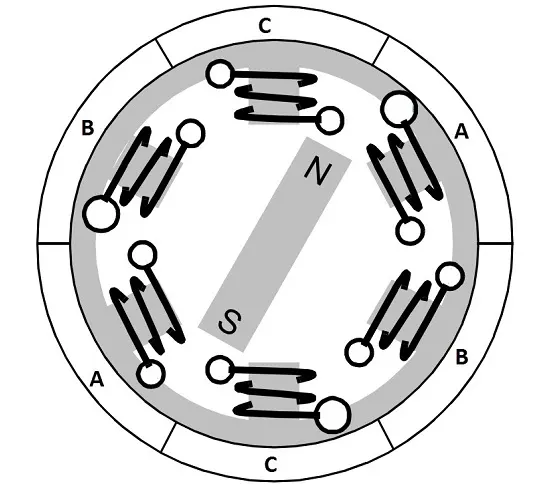
Figure 14.
Reference: Basics of Brushless DC Motors (BLDC Motors) | Construction, Working (electronicshub.org)