Week-6 Challenge: EV Drivetrain
Ques 1.
The converters used in electric and hybrid electric vhicles are:
- DC-DC converter (Chopper) - Used to power low voltage auxilary systems
- AC-DC converter (Rectifier) - Used to convert utility AC power to DC power for vehicle charging
- DC-AC converter (Inverter) - Used to convert DC voltage fom battery pack to variable AC voltage that is used to power the drive PMSM or induction motor
Ques 2.
The Matlab script shown in Figure 1 (Motor_Chopper.m) is used to generate the plots of Motor torque and Vehicle torque versus motor speed.
The following equation is used to describe the relationship between the Motor Torque (Te) and Motor Speed (w). Notice that the acceleration duty cycle is multiplied by the rated battery voltage to obtain the average output voltage from the chopper, which is the average voltage input to the motor. Note that it is assumed that the time constant of the armature circuit is several order of magnitude greater than the chopper switching period. If this is true, the armature current is always continuous.
`Te=(Km*d1*Vt)/(Ra)-(Km^2*wm)/(Ra)`
where
`Km` - motor torque and speed constant
`d1` - Chopper acceleration duty cycle
`Ra` - armature resistance
The vehicle torque load is given as:
`Tv=24.7+0.0051w^2`
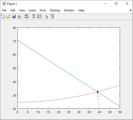
The intersection between the Motor torque and Vehicle torque when plotted versus motor speed is used to determine the steady state speed of the motor. This is illustrated in Figure 2.
Based on the motor data provided, the motor steady-state speed is determined by solving the Motor torque and Vehicle torque equations simultaneously. Thus, solving the following quadratic equation for the positive real solution yields steady-state speed of 38.92 rad/s or 371.6 RPM.
`0.0051w^2+0.98w-45.86=0`
Figure 1. Matlab script used to generate motor and vehicle load torque plots
clear;
clc;
close all;

Vbat = 72;      %Rated battery voltage (V)
Ra = 0.5;       %Armature resistance (ohms)
Km = 0.7;       %Motor speed and torque constant (V.s)
d1 = 0.7;       %Chopper duty cycle (70%)

w = 0:0.1:50;   %Speed range (rad/s)

Te = Km*d1*Vbat/Ra - Km^2*w/Ra; %Motor torque-speed expression
Tv = 24.7 + 0.0051*w.^2;        %Vehicle load torque-speed expression

plot(w,Te)      %plot of motor torque versus motor speed
hold on;
plot(w,Tv)      %plot of vehicle load torque versus motor speed
Figure 2. Plots of Motor Torque (blue) and Vehicle Load Torque (orange) versus Motor Speed
Ques 3.
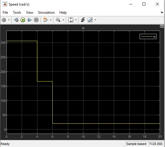
The Simulink for for the DC Motor equation is shown in Figure 3. The signal generator is used to vary the battery voltage input with time. Note that the speed is determined for fixed motor torque. Observe in Figure 4 that the motor steady-state speed reduces as the battery voltage is reduced.
Figure 3. DC Motor speed versus torque Simulink model
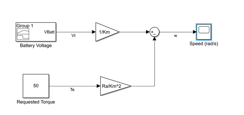
Figure 4. Plot of motor speed for fixed torque and variable battery voltage
Ques 4.
The author compares the merits of using brushless permanent motors and induction motors in electric and hybrid electric vehicles. He outlines the operating principle of each motor technology and presents their pros and the cons. However, the author could not identify a clear winner but projects that in the future each motor technology may be more suitable for certain types of electric vehicles and may even be applied in combination due to their simularities in stator construction, risk of the rising cost of permanent magnets, and the potential to derive the benefits of both technologies.