Week - 4
Ques 1.
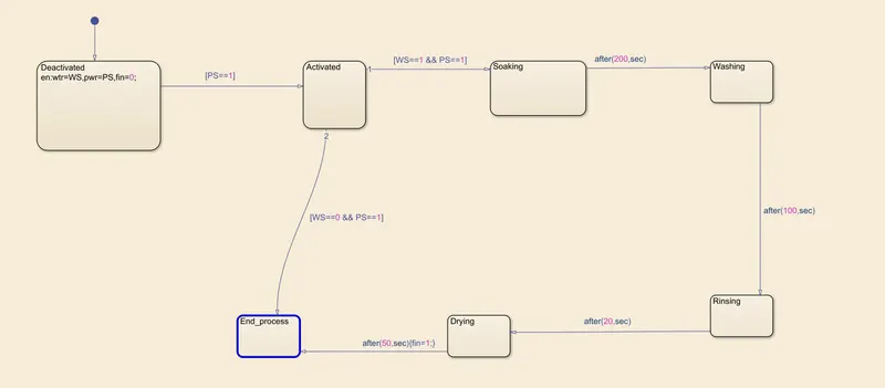
Objective: To implement a basic control logic of a washing machine in Stateflow.
Control logic:
- The system is activated when the power supply is available,
- When the power supply is available but the water supply is unavailable, the process is stopped prematurely and an LED is lit red to indicate this scenario,
- When the power and water supplies both become available, the washing cycle is initiated,
- The Soaking process starts after the power and water supplies become available and the tub has been filled,
- The Soaking process takes 200 seconds, after which the Washing cycle commences,
- The Washing process takes 100 seconds, after which the Rinsing process commences,
- The Rinsing process takes 20 seconds, after which the Drying process commences,
- The Drying process takes 50 seconds after which the washing cycle ends.
Assumptions:
- When power supply becomes available at the start of the simulation, it remains available throughout the simulation period.
- When the water supply becomes available at the start of the simulation, it also remains available throughout the simulation period.
- If the water supply is unavailable at the start of the simulation, it remains unavailable for the simulation period making it impossible to initiate the wash cycle even if the power supply is available.
- If the power supply is unavailable at the start of the simulation, it remains unavailable for the simulation period and causes the system to remain in a deactivated state.
- The complete wash cycle includes the Soaking, Washing, Rinsing and Drying processes.
- The wash cycle runs once, comes to a stop and wash cycle is not repeated.
Scenarios 1 to 4 below show that the washing machine stateflow model is accurate and consistent with the stated contro logic.
Results and figures: (Refer to attached Wk4_Wash_Machine.slx for details)
Scenario 1
Figure 1 below, illustrates the state of the system when the power and water supplies are both unavailable. Note that the water and power supply availability LEDs remain lit in red for the simulation period indicating that both supplies are unavailable.
Per Figure 2, note that the Deactivated process remains active for the entire simulation period.
Figure 1: Power and Water supplies both unavailable (Overview)
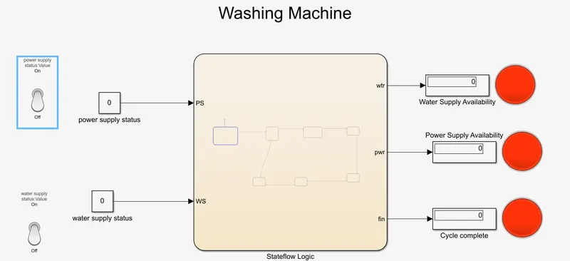
Figure 2: Power and Water supplies both unavailable (Detailed Chart)
Scenario 2
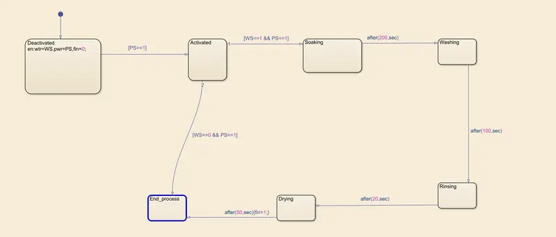
Figure 3 below, illustrates the state of the system when the power supply is available and the water supply is unavailable. Note that at the end of the simulation period, the water availability LED is red indicating that the water supply is unavailable and the power supply availability LED is green indicating that the power supply is available. Note that the cycle completion LED is red indicating that the wash cycle was not executed due to premature cycle termination.
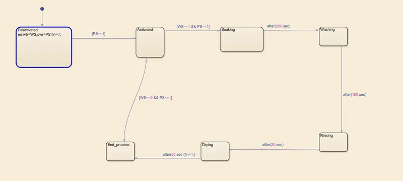
Per Figure 4, the state machine starts in the Deactivated process, moves through the Activated process and prematurely terminates in End_process due to the unavailability of water supply.
Figure 3: Power supply available and Water supply unavailable (Overview)
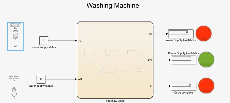
Figure 4: Power supply available and Water supply unavailable (Detailed Chart)
Scenario 3
Figure 5 below, illustrates the state of the system when the power supply is unavailable and the water supply is available. Note that at the end of the simulation period, the water availability LED is green indicating that the water supply is available and the power supply availability LED is red indicating that the power supply is unavailable. Note that the cycle completion LED is red indicating that the wash cycle was not executed. Note that the cycle completion LED is red indicating that the wash cycle was not executed.
Observe in Figure 6 that the Deactivated process remains active for the entire simulation period regardless of the water supply availability.
Figure 5: Power supply unavailable and Water supply available (Overview)
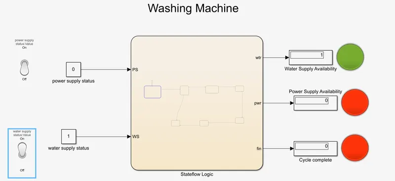
Figure 6: Power supply unavailable and Water supply available (Detailed Chart)
Scenario 4
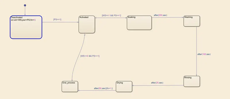
Figure 7 below, illustrates the state of the system when the power and the water supplies are both available. Note that at the end of the simulation period, the power and water availability LEDs are both green indicating that the water and power supplies are both available. Note that the cycle completion LED is green indicating that the wash cycle was completed.
In Figure 8, the state machine is initiated in the Deactivated process and moves through the Activated, Soaking, Washing, Rinsing and Drying processes before terminating in the End_process. The delays between the processes of the washing cycle are indicated in Figure 8, which alludes to the time allowed for the processes to run. For example, the Soaking process is allowed 200 secs after which the Washing process commences, etc.
Figure 7: Power and Water supplies both available (Overview)
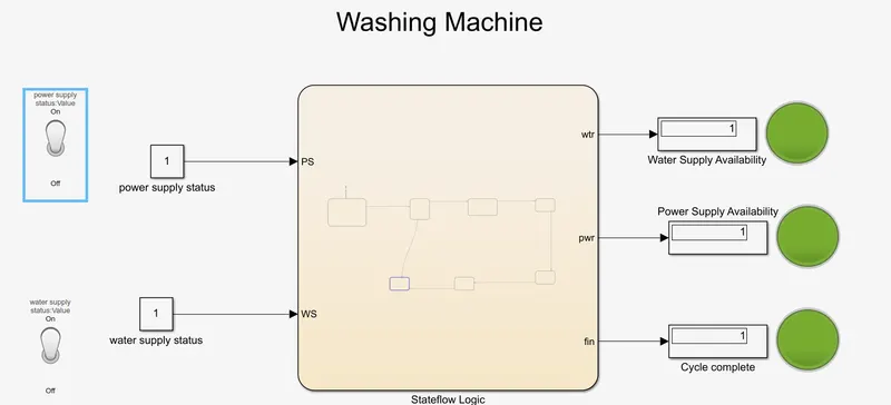
Figure 8: Power and Water supplies both available (Detailed Chart)
Ques 2.
Objective: To implement the control logic for Gear Shift system in Stateflow.
Control logic:
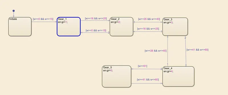
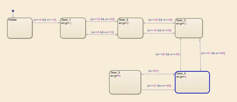
- When speed is greater than or equal to 0 km/h or less than or equal to 15 km/h, gear 1 should be engaged.
- When speed is greater than or equal to 16 km/h or less than or equal to 25 km/h, gear 2 should be engaged.
- When speed is greater than or equal to 26 km/h or less than or equal to 40 km/h, gear 3 should be engaged.
- When speed is greater than or equal to 41 km/h or less than or equal to 60 km/h, gear 4 should be engaged.
- When speed is greater than or equal to 61 km/h, gear 5 should be engaged.
Assumptions:
- The speed changes in increments of 1 km/h
- Gear shifts are monotonically increasing or decreasing with speed
- Simulation starts with speed equal to 0 km/h
Scenarios 1 to 5 below show that the stateflow as modelled for the Gear Shift system is accurate and consistent with the stated control logic.
Results and figures: (Refer to attached Wk4_Gear_Shift.slx for details)
Scenario 1
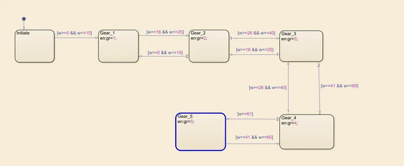
Figure 9 below shows an instant of the Gear Shift stateflow with speed equal to 5 km/h and the corresponding gear that is engaged. Note that gear 1 is engaged consistent with the stated control logic. Observe in Figure 10 that the Gear_1 process is highlighted as expected.
Figure 9: Speed = 5 km/h (Overview)
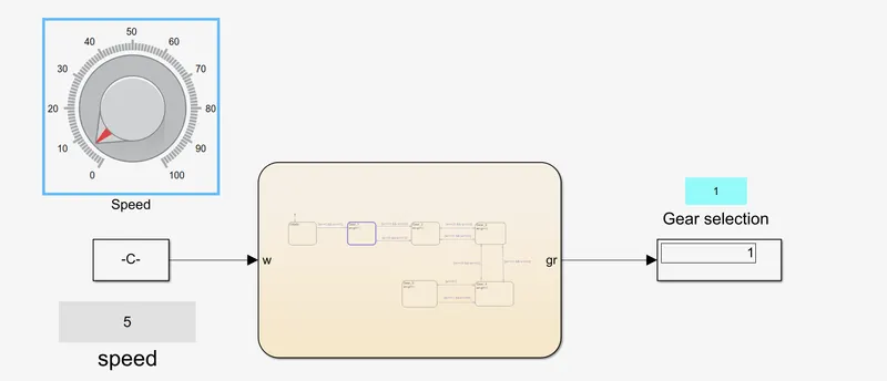
Figure 10: Speed = 5 km/h (Detailed Chart)
Scenario 2
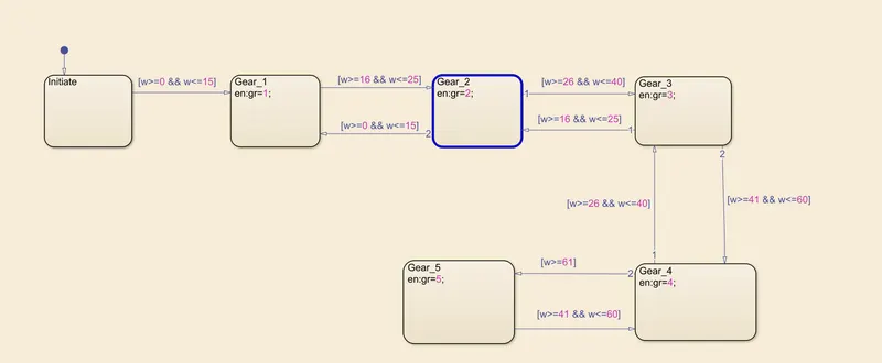
Figure 11 below shows an instant of the Gear Shift stateflow with speed equal to 20 km/h and the corresponding gear that is engaged. Note that gear 2 is engaged consistent with the stated control logic. Observe in Figure 12 that the Gear_2 process is highlighted as expected.
Figure 11: Speed = 20 km/h (Overview)
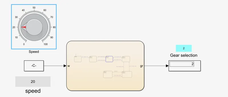
Figure 12: Speed = 20 km/h (Detailed Chart)
Scenario 3
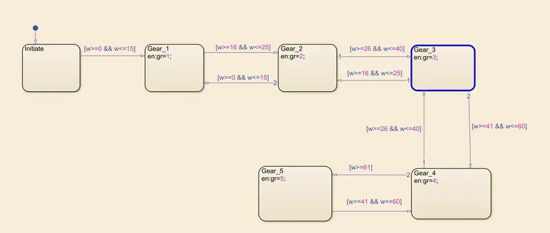
Figure 13 below shows an instant of the Gear Shift stateflow with speed equal to 30 km/h and the corresponding gear that is engaged. Note that gear 3 is engaged consistent with the stated control logic. Observe in Figure 14 that the Gear_3 process is highlighted as expected.
Figure 13: Speed = 30 km/h (Overview)
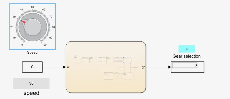
Figure 14: Speed = 30 km/h (Detailed Chart)
Scenario 4
Figure 15 below shows an instant of the Gear Shift stateflow with speed equal to 50 km/h and the corresponding gear that is engaged. Note that gear 4 is engaged consistent with the stated control logic. Observe in Figure 16 that the Gear_4 process is highlighted as expected.
Figure 15: Speed = 50 km/h (Overview)
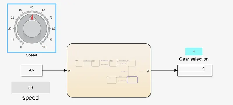
Figure 16: Speed = 50 km/h (Detailed Chart)
Scenario 5
Figure 17 below shows an instant of the Gear Shift stateflow with speed equal to 70 km/h and the corresponding gear that is engaged. Note that gear 5 is engaged consistent with the stated control logic. Observe in Figure 18 that the Gear_5 process is highlighted as expected.
Figure 17: Speed = 70 km/h (Overview)
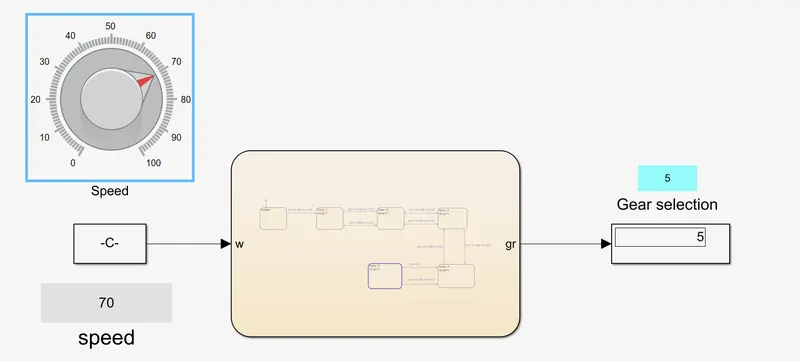
Figure 18: Speed = 70 km/h (Detailed Chart)