Week-7 Challenge: DC Motor Control
Aim: The following challenge has 3 exercises:
- A. Explain a MATLAB demo model named ‘Speed control of a DC motor using BJT H-bridge’. B. Comment on the armature current shoot-up from the scope results. C. Refer to the help section of ‘The Four-Quadrant Chopper DC Drive (DC7) block’. Compare it with the H-bridge model.
- Develop a 2-quadrant chopper using Simulink & explain the working of the same with the relevant results. (Refer to article - Multiquadrant operation of motor)
- Explain in a brief about operation of BLDC motor.
Software Used: Simulink. MS Word.
Solution:
- A. Explain a MATLAB demo model named ‘Speed control of a DC motor using BJT H-bridge’.
Here, 4 IGBT are connected in parallel with the motor connected in the centre which makes a H shape, making it a BJT H-bridge. The Bipolar Junction Transistor (BJT) when used for power switching applications, operates as an IGBT.
The H-bridge consists of four BJT/Diode pairs (BJT simulated by IGBT models). Two transistors are switched simultaneously: Q1 and Q4 or Q2 and Q3. When Q1 and Q4 are fired, a positive voltage is applied to the motor and diodes D2-D3 operate as free-wheeling diodes when Q1 and Q4 are switched off and the motor runs in a positive direction. When Q2 and Q3 are fired, a negative voltage is applied to the motor and diodes D1-D4 operate as free-wheeling diodes when Q2 and Q3 are switched off and the motor runs in a negative direction.
In this model, Motor speed, torque and current is calculated and plotted.
- B. Comment on the armature current shoot-up from the scope results.
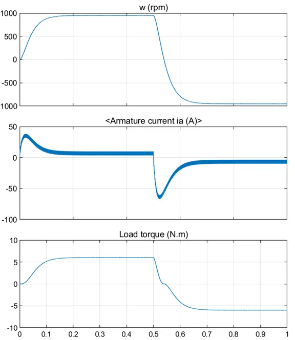
The positive armature current shoot-up is because of the load torque required to move the vehicle at the start. After the vehicle has reached the top speed and max. torque (and it is constant then after) the positive armature current reduces and is constant till Q2 and Q3 are fired. The same goes with negative current shoot-up as more torque is required to stop the vehicle.
- C. Refer to the help section of ‘The Four-Quadrant Chopper DC Drive (DC7) block’. Compare it with the H-bridge model.
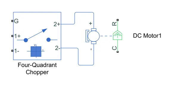
The Four-Quadrant Chopper DC Drive (DC7) block has a similar function compared to the H-bridge model but DC motor is not available in the block. We can connect DC motor to The Four-Quadrant Chopper DC Drive (DC7) block in the image shown below:
- Develop a 2-quadrant chopper using Simulink & explain the working of the same with the relevant results. (Refer to article - Multiquadrant operation of motor)
Program:
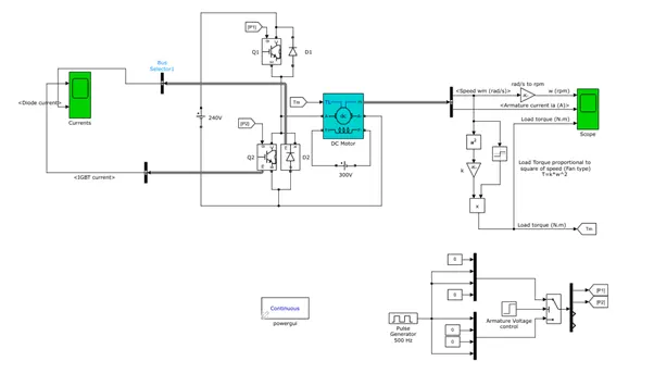
Here, when Q1 is fired, a positive voltage is applied to the motor and diode D2 operate as free-wheeling diodes when Q1 is switched off and the motor runs in a positive direction. When Q2 is fired, a negative voltage is applied to the motor and diode D1 operate as free-wheeling diodes when Q2 is switched off and the motor runs in a negative direction.
In this type of chopper, the average load voltage is always positive but the average load current can be positive or negative.
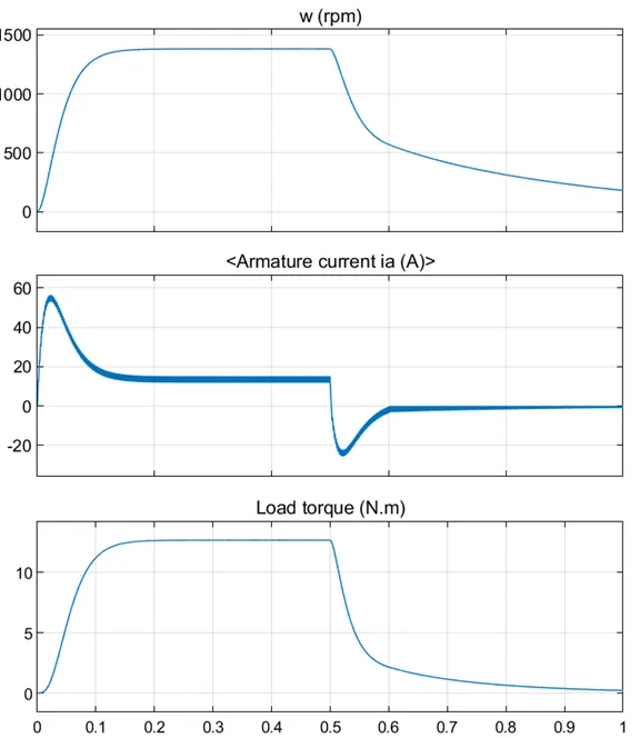
Results for 2-quadrant chopper:
- Explain in a brief about operation of BLDC motor.
BLDC motor works on the principle similar to that of a Brushed DC motor. The Lorentz force law which states that whenever a current carrying conductor placed in a magnetic field it experiences a force. As a consequence of reaction force, the magnet will experience an equal and opposite force. In the BLDC motor, the current carrying conductor is stationary and the permanent magnet is moving.
The following GIF is the working of a BLDC Motor. It contains a stator (which has windings) and a rotor which is a permanent magnet. When current is passed through the windings, it generates a magnetic field. The polarity of the magnetic field depends on the direction of the current. When the stator winding produces magnetic north polarity, the south pole of the permanent magnet rotor tries to connect to it. When the rotor is about to connect to the winding, the current flowing through the winding is switched off and the south pole of the motor passes through the winding due to inertia. Then the current flowing through the winding is reversed and winding produces magnetic south polarity which repels the south pole of the rotor. Similarly, the next winding does the same job and the rotor continues to rotate till current flows through the windings.