Week - 4
Aim: To create a Simulink Model by using Stateflow Chart for Washing Machine and Gear Shift for vehicles.
Control Logic of a “Washing Machine” using Stateflow:
The washing machine has been used for 1000 seconds and has performed the following operations:
- Soaking for 200 seconds.
- Washing for 100 seconds.
- Rinsing for 20 seconds.
- Drying for 50 seconds.
Simulink Model:
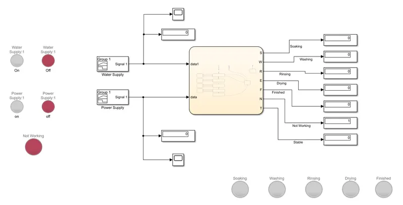
Blocks Used:
- Signal Builder.
- Display
- Scope
- Stateflow Chart.
- Lamp
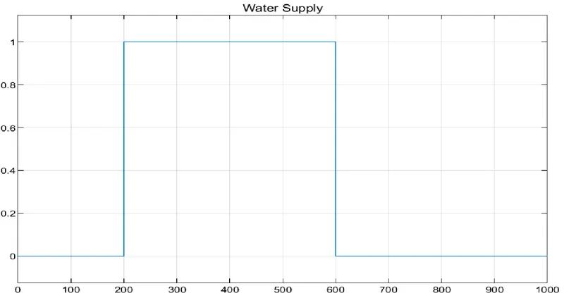
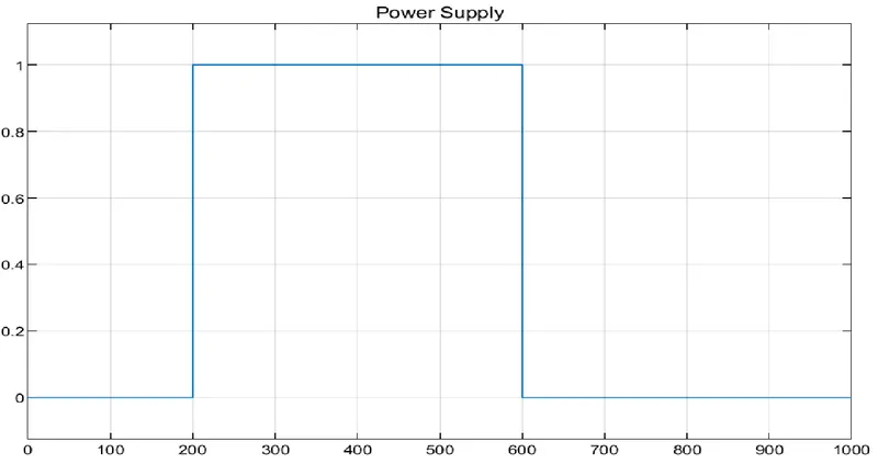
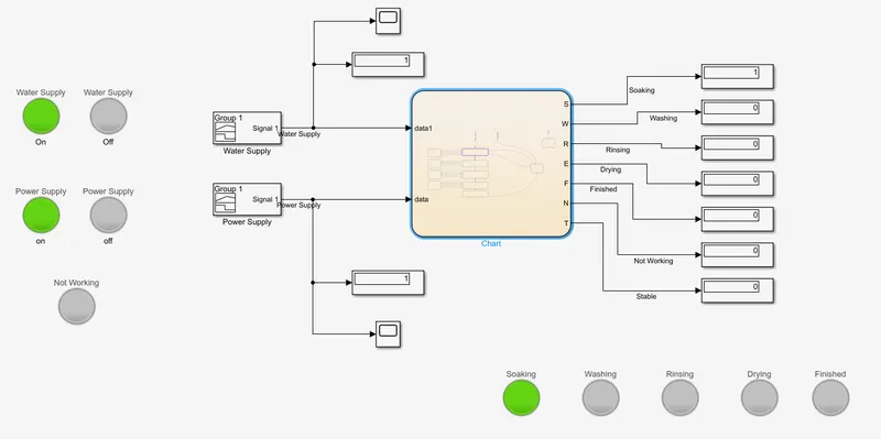
Signal Builder is used for Water and Power Supply. Here, 0 means the supplies are switched off and 1 means the supplies are switched on. Scope and Display blocks are connected to the Signal Builder to measure the Water and Power Supply. Signal Builder is then connected to the Stateflow Chart.
Water Supply Plot:
Power Supply Plot:
Stateflow Chart:
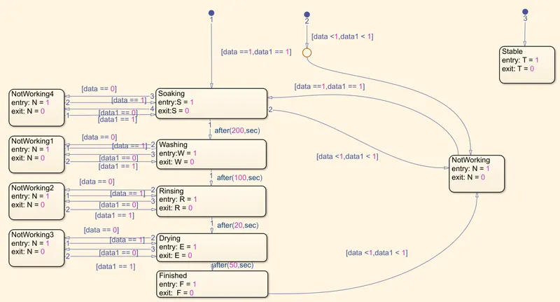
Here, data is Power Supply and data1 is Water Supply. When data and data1 is 1, the washing machine starts it operation as shown in the chart.

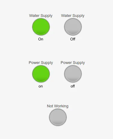
When data and data1 is 0, the compiler will go to the not working chart and the machine will not start until the water and power supply is restored. The machine will not start when there is no power supply even if water supply is available and the Not Working Lamp will glow.
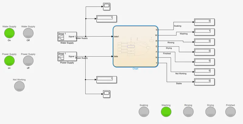
The Lamps of Soaking, Washing, Rinsing and Drying will glow when each of these processes is being carried out by the machine. When all the processes are done, the Finished Lamp will glow until the power supply is switched off.
Soaking:
Washing:
Rinsing:
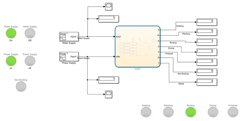
Drying:
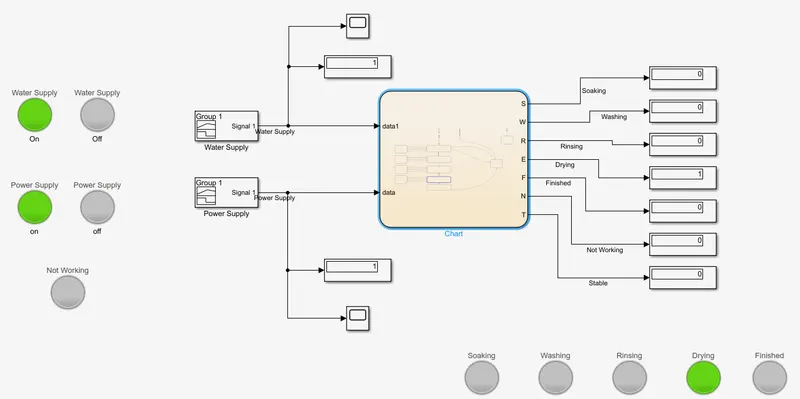
Finished:
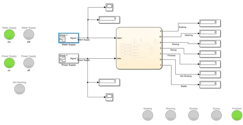
There are Not Working Chart beside the operation charts of the washing machine, so that if the power or water supply is stopped in between the processes the Not Working Lamp will glow at that process and the machine will stop working. The machine will start working at that process where it stopped when the power and water supply is restored.
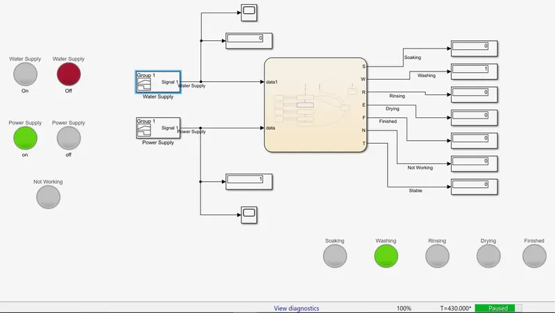
Here, the water supply was cut off at 420th second, when the machine was operating the process of washing.
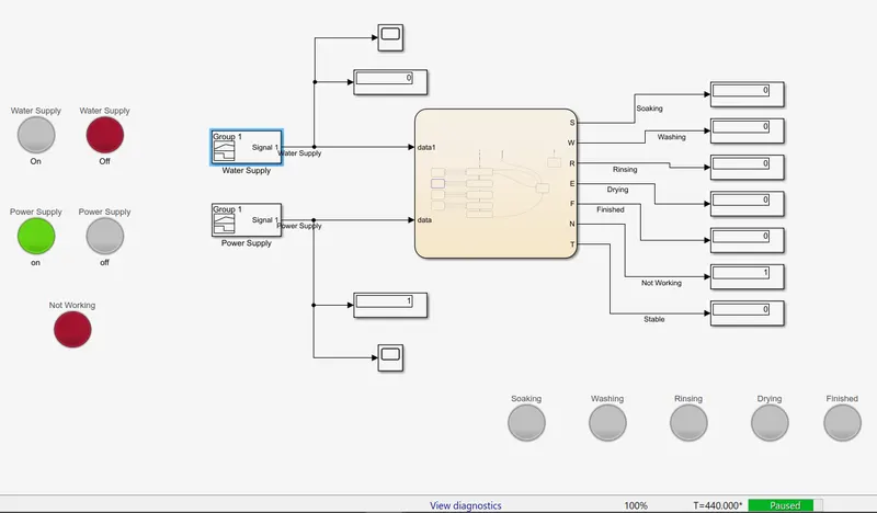
The machine stopped working after the water supply was cut off. The machine will start the operation from it stopped when the water supply is available.
If the power supply is available but the water supply is not available, then the machine will start operating but will stop at the moment it starts soaking and the Not Working Lamp will glow along with the Soaking Lamp. The machine will start working when the water supply is available.
Simulink chart for the “Gear shift” logic:
The gear must be shifted when the vehicle reaches a particular speed:
Speed Range (kmph) Gear
0 to 15 1
16 to 25 2
26 to 40 3
41 to 60 4
Above 61 5
Simulink Model:
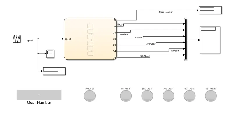
Blocks Used:
- Repeating Sequence.
- Display
- Scope
- Stateflow Chart.
- Lamp
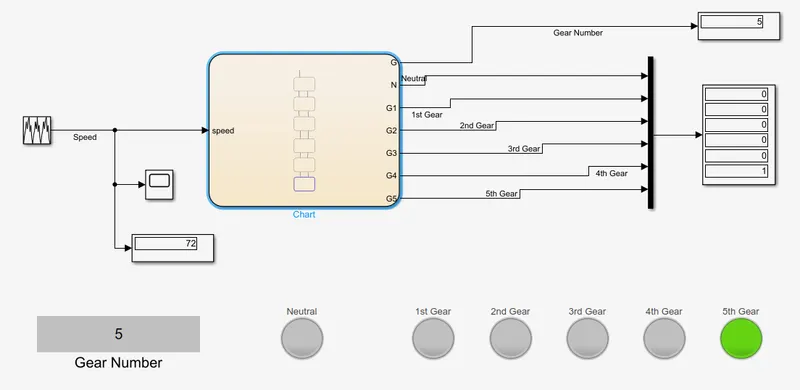
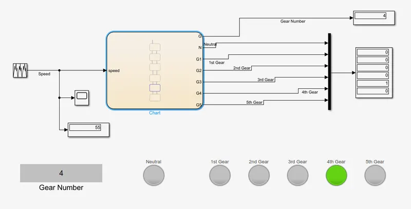
Repeating Sequence is used for vehicle speed and the vehicle is run for 100 seconds. The speed of the vehicle is measured using the Scope and Display Blocks. The Repeating Sequence is then connected to the Stateflow Chart.
Repeating Sequence Plot:
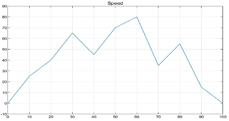
Speed of the vehicle for 100 seconds.
Stateflow Chart:
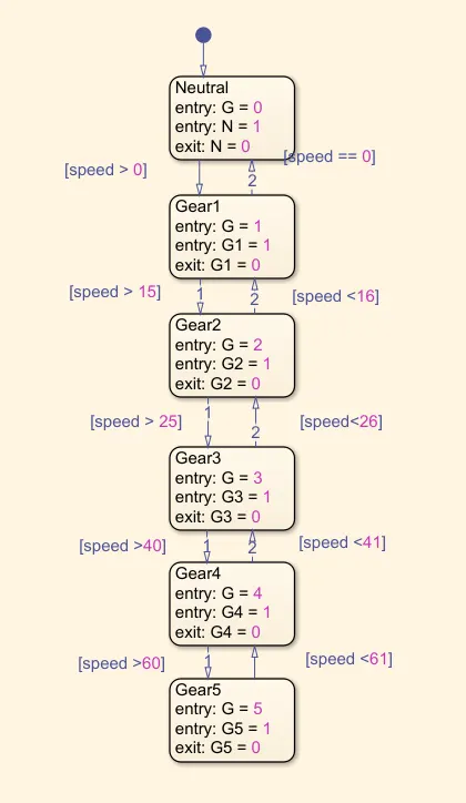
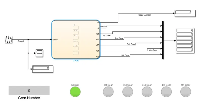
Here, Neutral is used when the vehicle is at 0 kmph speed. When the vehicle accelerates, the following gears gets activated to the following speed:
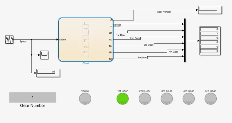
- 1st Gear at 0-15 kmph.
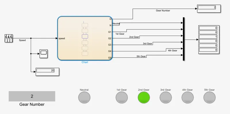
- 2nd Gear at 16-25 kmph.
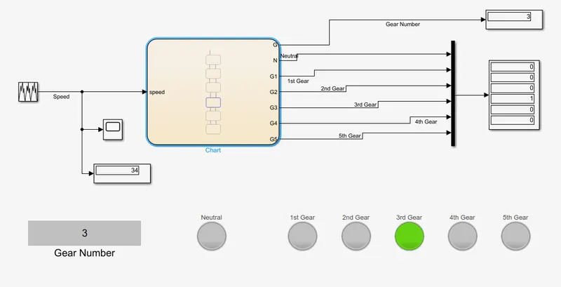
- 3rd Gear at 26-40 kmph.
- 4th Gear at 41-60 kmph.
- 5th Gear at 60 kmph and above.
Variables:
G = (0, 1, 2, 3, 4, 5) Gear Number.
N = 0 - Neutral.
G1, G2, G3, G4, G5 = The respective gear gets activated when it is equal to 1 and deactivated when it is equal to 0. When any of the gear is equal to 1, then the respective Lamp will glow and also will show the respective gear in the Gear Display block as the variable G will be equal to the respective Gear.
Neutral:
1st Gear:
2nd Gear:
3rd Gear:
4th Gear:
5th Gear: