Week -2
Aim: To make a Simulink model of doorbell with solenoid.
Theory: Components used in a doorbell:
The circuit for a doorbell is shown in the figure below:
Working:
When the Switch is turned on, the solenoid acts as an electromagnet by using the electric current from the battery, which attracts the hammer (which is made of iron) towards it. As the hammer acts as wire in the above circuit, when the solenoid attracts the hammer towards it, the electric supply breaks, due to which the solenoid releases the hammer and the hammer gets connected to the wire again. Because of this phenomenon, the hammer hits the bell as long as the switch is turned on.
Simulink Model:
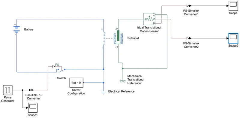
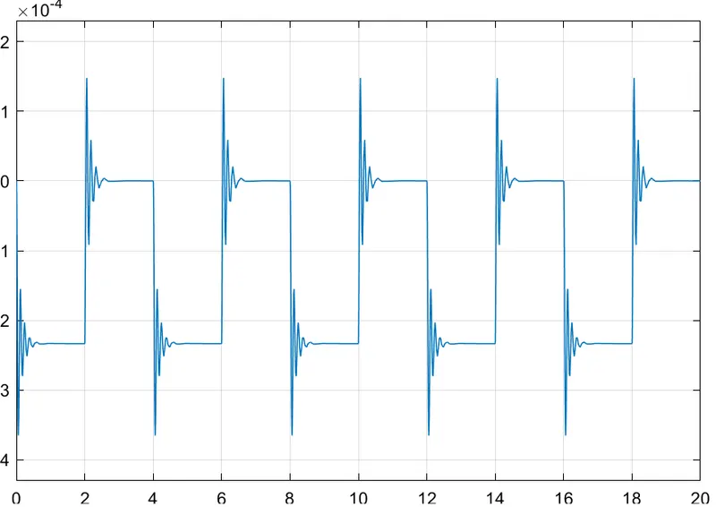
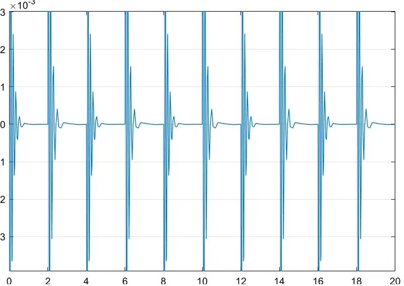
Here, both the terminals are connected to the solenoid. The solenoid vibrates when electricity is passed through it and this vibration is recorded using the ideal translation motion sensor block which record the position of the hammer from port R to port C (port C is the position of the bell) in the ideal translation motion sensor block. Port V calculates the velocity of the hammer.
The Pulse Generator generates pulses for every 2 seconds which makes the switch on for 2 sec and this is done up to 20 seconds.
Position of the Hammer up to 20 seconds:
Velocity of the Hammer up to 20 seconds:
Pulse Generator:
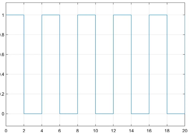
Here, 1 means to on the switch and 0 means to off the switch.
Heater Temperature sensing using Thermistor.
Aim: To sense the temperature of a Heater and to turn on the fan when temperature is above 25 degC.
Theory:
- Thermistor: A thermistor is defined as a type of resistor whose electrical resistance varies with change in temperature.
There are two types of thermistors:
- Negative Temperature Coefficient (NTC) Thermistor:
In an NTC thermistor, when the temperature increases, resistance decreases.
- Positive Temperature Coefficient (PTC) Thermistor
In a PTC Thermistor, when temperature increases, the resistance increases.
In this Model, a NTC thermistor is used.
Simulink Model:
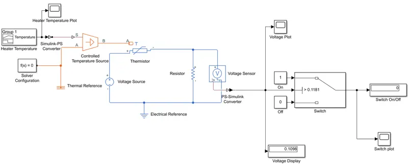
Here a signal builder is used to for Heater Temperature as per the conditions of the challenge 20 °C from 0 to 10 seconds, 27 °C from 10 to 30 seconds, 23 °C from 30 to 50 seconds.
Signal Builder plot:
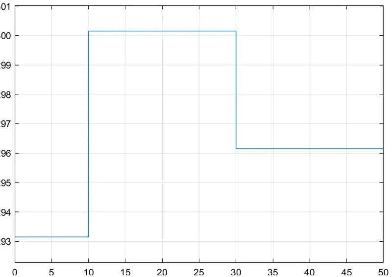
The signal builder is connected to the controlled temperature source which is connected to the thermal reference. The temperature at the thermal reference is set to 0 K and the sum of the temperature of the signal builder and the thermal reference is passed to the Thermistor.
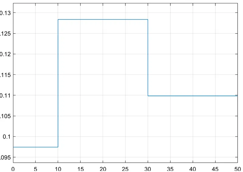
The thermistor is connected to the voltage source and the resistance is developed in the thermistor due to the voltage source and the control temperature source. A second resistor is connected in series with the thermistor and a voltage sensor is connected to it to check the voltage across the resistor. As the thermistor is of NTC type, the voltage sensor cannot be connected to the thermistor as it would give less voltage readings for higher temperatures. The resistor connected in series would give higher voltage values at higher temperature. The voltage indicated at 25 degC (298.15 K) is set at the switch and constants 1 and 0 are also connected to it. For temperatures above 25 degC, the switch will pass the value 1 and the fan will be turned on and vice versa.
Voltage Plot:
Switch Plot:
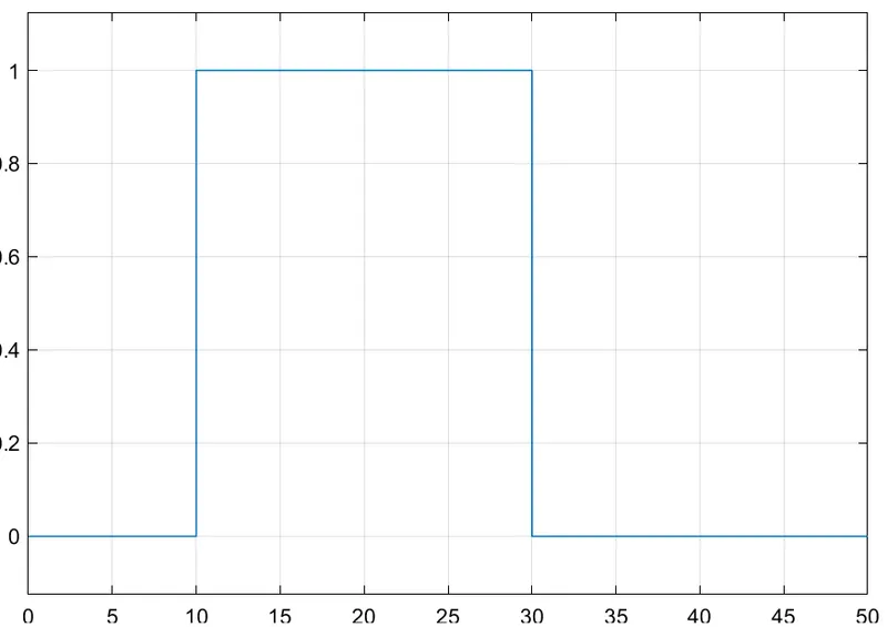
Here, we can see that the switch is on between time 10-30 seconds as the temperature increased above 25 degC.