Week-7 Challenge: DC Motor Control
1. A. Explain a MATLAB demo model named ‘Speed control of a DC motor using BJT H-bridge’.
B. Comment on the armature current shoot-up from the scope results.
C. Refer to the help section of ‘The Four-Quadrant Chopper DC Drive (DC7) block’. Compare it with the H-bridge model.
Before going to the Model Explanation we can understand the construction and the operation of BJT(Bipolar junction Transistor) and IGBT(Insulated Gate Bipolar Transistor) which has been used as an H-bridge in this MATLAB model
Bipolar junction transistor(BJT)
A bipolar junction transistor (BJT) is a bidirectional device that uses both electrons and holes as charge carriers. While Unipolar transistor i.e. field-effect transistor uses only one type of charge carrier. BJT is a current controlled device. The current flows from emitter to collector or from collector to emitter depending on the type of connection. This main current is controlled by a very small current at the base terminal.
Construction
A bipolar junction transistor is formed by the combination of two back-to-back doped semiconductor materials. In other words, BJT is formed by the “sandwich” of back to back extrinsic semiconductor materials. These extrinsic semiconductors are PN junction diodes. Two PN junctions’ diodes are sandwiched together to form a three-terminal device knows as a BJT transistor. BJT is a three-terminal device having two junctions.
After doping an intrinsic semiconductor with Trivalent or Pentavalent impurities a P-type semiconductor or N-type semiconductor respectively is made. If the number of electrons is greater than the number of holes (positive carriers) then that is known as N-type semiconductor material. While in P-type semiconductors, the number of holes is greater than the number of electrons. When P-type and N-type material are connected together then it becomes a PN-junction diode. BJT transistors are formed after connecting two PN junctions back to back. These transistors are known as PNP or NPN bipolar junction transistors depending on whether P or N-type is sandwiched.
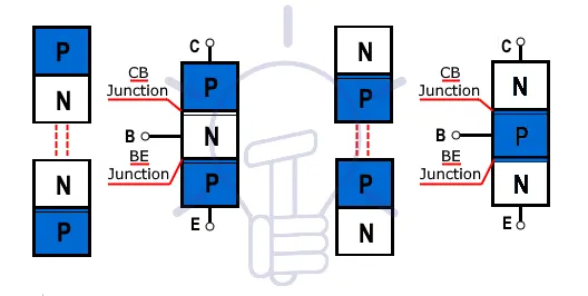
Types of BJT
This three-layer device formed by back to back connection has specific names. It can be whether PNP or NPN. Both connections are disused here briefly.
PNP Construction
In PNP bipolar transistor, the N-type semiconductor is sandwiched between two P-type semiconductors. PNP transistors can be formed by connecting cathodes of two diodes. The cathodes of the diodes are connected together at a common point known as the base. While the anodes of the diodes that are on the opposite sides are known as the collector and the emitter.
The emitter-base junction is forward bias while the collector-base junction is reverse bias. So, in PNP type current flows from emitter to collector. The emitter, in this case, is at the high potential for both collector and base.
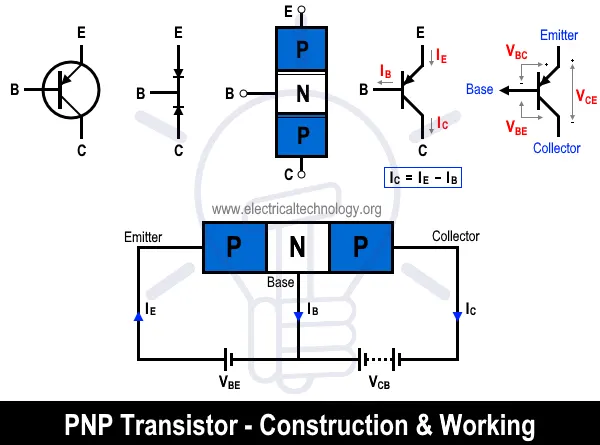
NPN Construction
NPN type is exactly opposite to PNP type. An NPN bipolar transistor, the P-type semiconductor is sandwiched between two N-type semiconductors. When the anodes of two diodes are connected together it forms an NPN transistor. The current will flow from the collector to the emitter because the collector terminal is more positive than the emitter in the NPN connection.
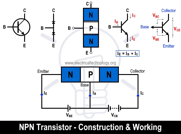
The difference between PNP and NPN symbols is the arrow mark at the emitter which shows the direction of flow of current. The current will either flow from emitter to collector or from collector to emitter. The arrow mark in the PNP transistor is inward, which shows the flow of current from emitter to collector. In the case of the NPN collector, the arrow mark is outward, which shows the flow of current from collector to emitter.
Working of BJT
The word “transistor” is the combination of two words, “Trans” (Transform) and “istor” (Varistor). So, it means the transistor can transform its resistance. The resistance varies in such a way that it can either act as an insulator or conductor by applying a small signal voltage. This changing ability makes it able to perform both as an “Amplifier” or a “Switch”. It can be used either as a switch or an amplifier at a single time. Therefore, BJT can operate in three different regions to perform the said operation.
Active Region:
In the Active region, one of the junctions is in a forward bias while the other is in reverse bias. Here, the base current Ib can be used to control the amount of collector current Ic. Therefore, the active region is used for amplification purposes where the BJT acts as an amplifier with a gain β using the equation;
ic = β x Ib
It is also known as the linear region. This region is in between the cutoff region and the saturation region. The normal operation of BJT occurs in this region.
Saturation Region:
In the saturation region, both of the junctions of the BJT are in forwarding bias. This region is used for the ON-state of a switch where;
ic = isat
Isat is the saturation current & it is the maximum amount of current flowing between emitter and collector when BJT is in a saturation region. Since both junctions are in forwarding bias so, BJT acts as a short circuit.
Cutoff Region:
In the cutoff region, both junctions of a BJT are in reverse bias. Here the BJT work as off state of a switch where
ic = 0
The operation in this region is completely opposite to the saturation region. There are no external supplies connected. There’s no collector current and hence no emitter current. In this mode, the transistor acts as an off-state of the switch. This mode is achieved by reducing base voltage less than both emitter and collector voltage.
Vbe < 0.7
Insulated Gate Bipolar Transistor(IGBT)
The below picture shows the Demo model of the speed control of DC motor using BJT H-Bridge here we are used H-Bridge to generate the chopped voltage and to control the speed of the DC motor
In this model, we have used an IGBT H-Bridge instead of a BJT because The Bipolar Junction Transistor (BJT) when used for power switching applications, operates as an IGBT
When it is conducting (BJT operating in the saturated region), a forward voltage Vf is developed between collector and emitter (in the range of 1 V). Therefore, the IGBT block can be used to model the BJT device.
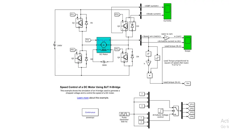
Here we are using four IGBT with four Diodes connected in pairs where these transistors are switched simultaneously when Q1 and Q4 switched ON which gives positive voltage to the motor and Q2 and Q4 switched ON gives negative voltage to the motor where D1, D2, D3, D4 acts as freewheeling in their respective switching modes this IGBT arrangement is in H-shape hence it is called as H-Bridge
Here we are using the switch block for controlling the IGBT in the model this switch block is controlled by the pulse generator where the duty cycle is given by default and the motor field voltage is connected to 300V battery and the mechanical torque of the motor is known as the square of the speed of the motor and the speed of the motor is converted from rad/sec to rpm and the speed of the motor, torque and the armature current is connected to the scope
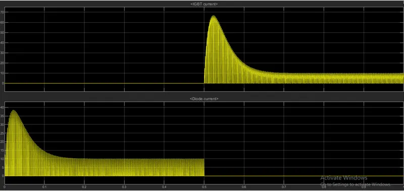
the Diode Current and the IGBT current is connected to the output of the scope shown below
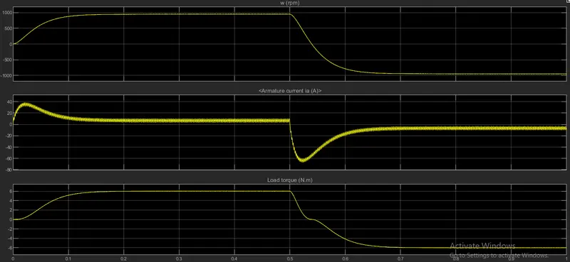
In the above plot, the armature current has a sudden rise and drop when the motor changes the direction from forward to reverse and the diode and IGBT current during the operation has shown in the output plot
The below Simscape block shows the four-quadrant Dc chopper Drive and its inside construction
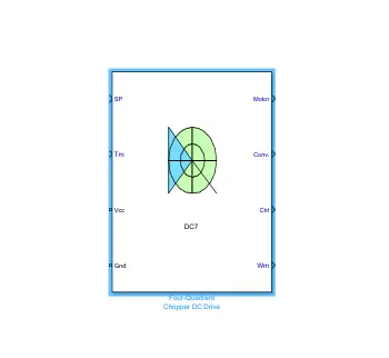
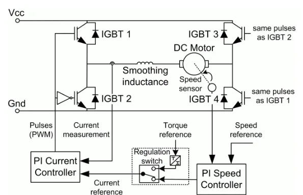
The Four-Quadrant Chopper DC Drive block represents a four-quadrant, DC-supplied, chopper (or DC-DC PWM converter) drive for DC motors. This drive features closed-loop speed control with a four-quadrant operation. The speed control loop outputs the reference armature current of the machine. Using a PI current controller, the chopper duty cycle corresponding to the commanded armature current is derived. This duty cycle is then compared with a sawtooth carrier signal to obtain the required PWM signals for the chopper.
The main advantage of this drive, compared with other DC drives, is that it can operate in all four quadrants (forward motoring, reverse regeneration, reverse motoring, and forward regeneration). In addition, due to the use of high switching frequency DC-DC converters, a lower armature current ripple (compared with thyristor-based DC drives) is obtained. However, four switching devices are required, which increases the complexity of the drive system
- The four-Quadrant chopper can operate in all four modes(Forward Motoring, Forward Braking, Reverse motoring, Reverse Braking) where H-Bridge can only operate in two modes
- regenerative braking is possible in Four-Quadrant operation but regenerative braking is not possible in H-Bridge Operation
- The Four-Quadrant DC chopper Gives better efficiency than H-Bridge
2. Develop a 2-quadrant chopper using Simulink & explain the working of the same with the relevant results.
The 2-Quadrant chopper model has been created using the Simulink has been shown below
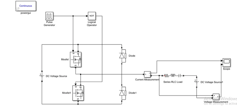
The pulse Generator block has been used for generating the gate signals to the MOSFET and the 24V DC voltage source is connected across the MOSFET and the Freewheeling diodes
The NOT gate is used in the model so that the two MOSFET will not get closed at the same time otherwise short circuit will occur, the amplitude of the pulse generator is kept at 10 so that we can see the pulses at the scope and the period is 1 sec and the pulse width is 50%
the 2-Quadrant chopper is obtained by connecting the two type-A and type-B chopper in parallel when the chopper is on freewheeling diode starts conducting and the output voltage equals to the input voltage the direction of the load current will be reversed the load current will be negative if the chopper diode D2 conducts
the average voltage will be always positive but the load current might be positive or negative
the below plot shows the output of the model simulation
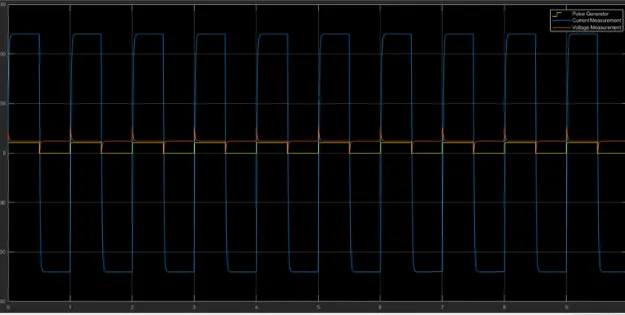
The voltage waveform is not going less than zero the minimum value of the voltage is zero and the maximum voltage value is always in the positive
3. Explain in a brief the operation of the BLDC motor.
BLDC motor works on the principle similar to that of a conventional DC motor, i.e., the Lorentz force law which states that whenever a current-carrying conductor is placed in a magnetic field it experiences a force. As a consequence of the reaction force, the magnet will experience an equal and opposite force. In the case of, BLDC motor, the current-carrying conductor is stationary while the permanent magnet moves.
When the stator coils are electrically switched by a supply source, it becomes an electromagnet and starts producing the uniform field in the air gap. Though the source of supply is DC, switching makes to generate an AC voltage waveform with a trapezoidal shape. Due to the force of interaction between the electromagnet stator and the permanent magnet rotor, the rotor continues to rotate.
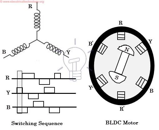
Consider the figure below in which the motor stator is excited based on different switching states. With the switching of windings as High and Low signals, corresponding winding energized as North and South poles. The permanent magnet rotor with North and South poles align with stator poles causing the motor to rotate.
Observe that the motor produces torque because of the development of attraction forces (when North-South or South-North alignment) and repulsion forces (when North-North or South-South alignment). In this way motor moves in a clockwise direction.
Brushless DC Motor Drive
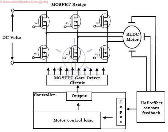
As described above that the electronic controller circuit energizes appropriate motor winding by turning transistors or other solid-state switches to rotate the motor continuously. The figure below shows the simple BLDC motor drive circuit which consists of a MOSFET bridge (also called an inverter bridge), electronic controller, hall effect sensor and BLDC motor.
Here, Hall-effect sensors are used for position and speed feedback. The electronic controller can be a microcontroller unit or microprocessor or DSP processor or FPGA unit or any other controller. This controller receives these signals, processes them and sends the control signals to the MOSFET driver circuit.
Advantages of DLDC motors
- High efficiency due to use of permanent magnet rotor
- Less electromagnetic interference
- Quiet operation (or low noise) due to absence of brushes
Disadvantages
- These motors are costly
- The electronic controller required to control this motor is expensive
- Not much availability of many integrated electronic control solutions, especially for tiny BLDC motors
- Requires complex drive circuitry
- Need of additional sensors