Simulink of Washing Machine & Gear_Shift model using State flow and control logic
Simulink Model of a Washing Machine
By using the below conditions we have created the Simulink model of a washing machine
- If the power supply is available, the system gets activated
- If the Water supply is not available, stop the process & indicate through LED
- Soaking time should be 200s followed by Washing time of 100s.
- Then rinsing happens for next 20s & dryer runs for 50s
The below diagram shows the Simulink model and block diagram of the washing machine here we have used the state flow and control logic concept to create the model using block diagrams.
Simulink Model:
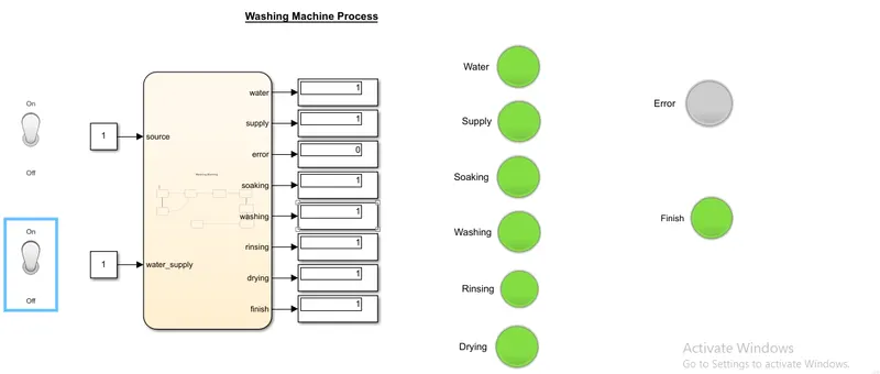
Explanation:
When the Source & water_supply has turned then it moves to soak for 200Sec after that it movies to washing for 100Sec after that it moves to rinse for 50Sec after that it movies to Drying for 20Sec then it completes the washing Process and shows the Finish signal as shown above model
State flow Diagram:
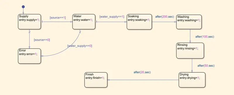
Explanation:
Here we are using blocks with some conditions if that condition satisfy then it moves to another state like if the source equals to 1 then the supply will turn on and it will check if water equals to 1 then soaking has done for 200Sec after that washing has done for 100Sec and so on till the washing process has reached to finish
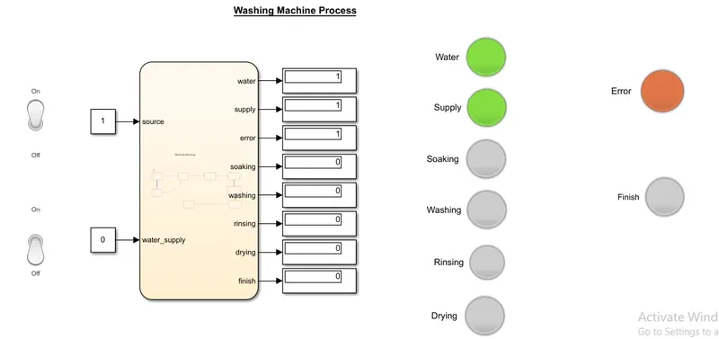
- If the water is not available and the supply is available then it will show the error indication as shown below the diagram and the washing stopped at the initial stage
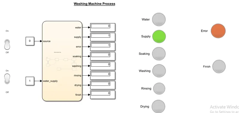
- if the supply is not available and water is available then it will show the error indication as shown below and washing has stopped
Simulink model for the Gear shift
Here we are making gear transmission using the state flow and we are changing the gear in different speed range as shown below
Speed Range(kmph) Gear
0 to 15 1
16 to 25 2
26 to 40 3
41 to 60 4
Above 61 5
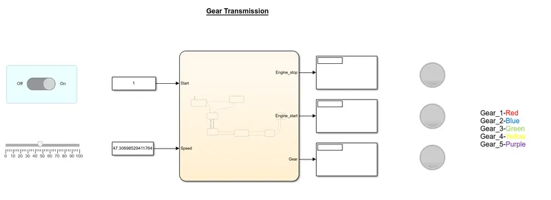
Below Diagram shows the Simulink and state flow model of the Gear shift
Simulink model:
State Flow Diagram:
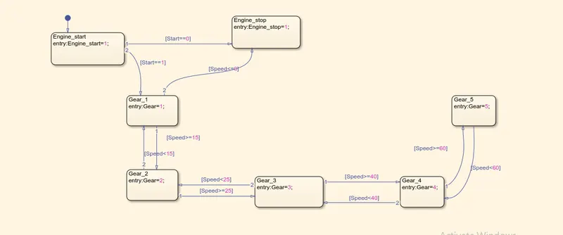
Explanation:
- By using a switch we are giving input signal to start the gear_shift then by using slider block we are changing the speed while running the simulation
- Below diagram shows the simulation of gear_shift by changing the speed with respect to change in Gear
- Here we are running the simulation inf time.
Initially, the engine has started and the speed is 0 which is represented by a green LED as shown below
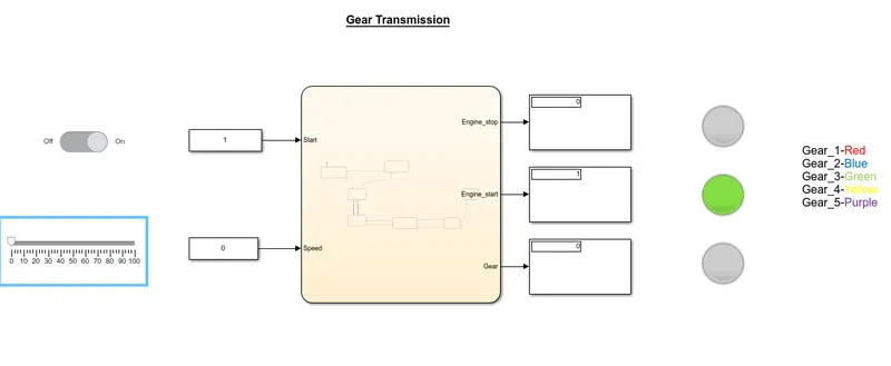
Then by varying the speed the gear has been shifted from one gear to another that has been shown below Diagrams.
At Gear_1
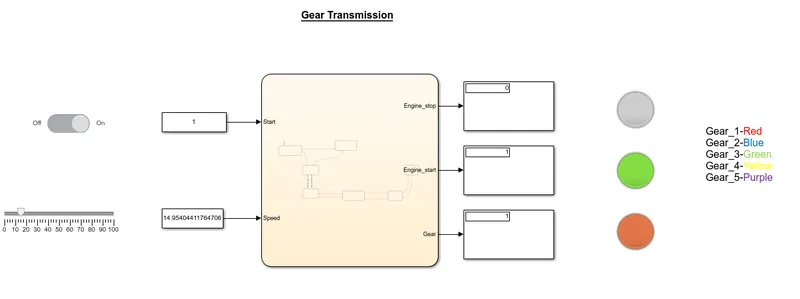
At Gear_2
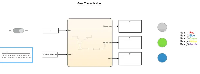
At Gear_3
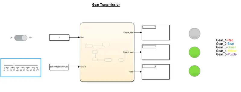
At Gear_4
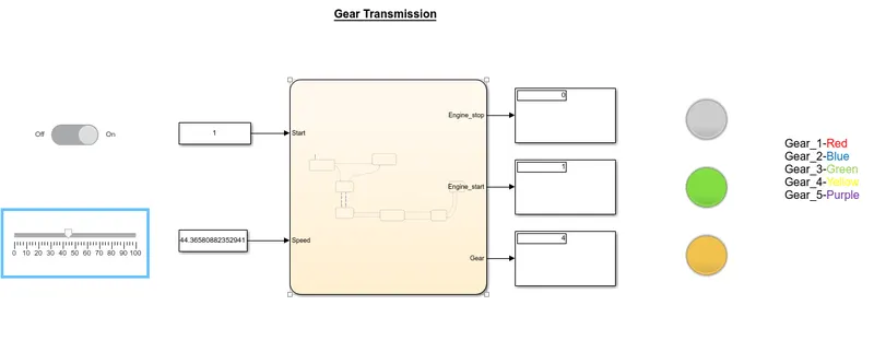
At Gear_5
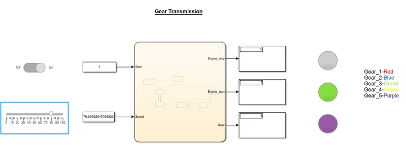
Learnings:
- from the above models, we can learn how to write state flow charts and that can be used in different applications
- How to create the Simulink models using Simulink blocks and state flow charts.