Week-7 Challenge: DC Motor Control
Q1. A. Explain a MATLAB demo model named ‘Speed control of a DC motor using BJT H-bridge’-
The following model was found with the search keywords:
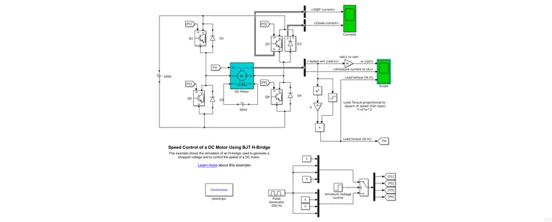
Here we can see the following blocks-
DC Motor-
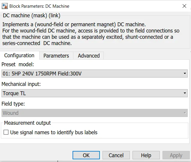
This represents the fan load which follows `T=komega^2`. It is fed by armature voltage of 240V which can be varied from 0-240V depending on the duty cycle. Its excited by a field voltage of 300V.
H Bridge-
The H-Bridge is made by the arrangement of 4 IGBT/Diode pairs in the shape of an H as shown in the figure. They are named as Q1/D1, Q2/D2, Q3/D3 and Q4/D4. The diodes are called as Free wheeling diodes which are used to protect the switches from high currents and voltages during switching operation. The IGBTs are triggered by a firing circuit which has a pulse generator and armature voltage controller. The duty cycle is 75%.
Working principle-
The H bridge is used to vary the amount and polarity of voltage applied to the motor from a fixed DC source. This helps to control the motor's speed and direction of running.
Lets analyze case 1 when Q1 and Q4 are triggered:
In this case positive current flows through the motor armature and motor runs in forward direction. Also some leakage currents flow through the diodes D2 and D3.
Case 2: Q2 and Q3 are triggered
Here, negative current flows through the motor armature and it starts running in opposite direction. During this time leakage currents flow through D1 and D4.
Results:
After running the simulation for 1 sec, the following graphs were achieved-
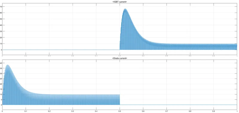
These are the currents through Q3/D3. We see a spike in the currents during the switching due to the inductance present in the DC motor causing leakage and also back EMF of the motor.
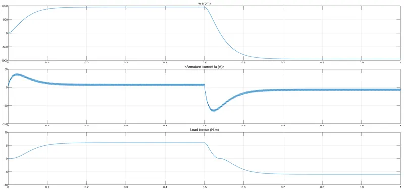
B. Armature current shoot ups-
We know that when a current passes through the armature of the motor, a back emf is generated which will be opposite to the supply voltage. When we switch the polarity of supply, the new current will be added up with current due to back emf and we will get the momentary spike. But it soon dies off as they back emf would also have changed its direction. This peak is very dangerous and can burn off fuses and spoil the microcontroller devices.
C. Four Quadrant Chopper Dc Drive:
The following is the arrangement of a four quad chopper drive system:
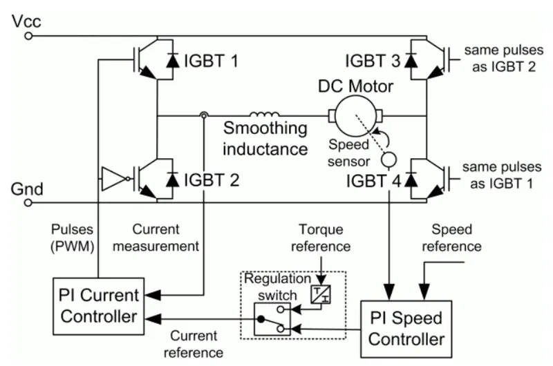
This drive consists of 4 IGBT/Diode sets and a smoothing inductance connected in series with the Dc motor. It also consists of a speed sensor and current sensor which feeds to ther respective controllers. The controllers try to manage the speed and current to reference values. It's a closed loop system. Now lets understand the 4 quadrant operation:
1. Forward motoring(First quadrant):
This happens when IGBT1 and IGBT4 are triggered. The motor experiences positive current and voltage.
But if IGBT1 is switched off then current flows IGBT4 and D2.
2. Forward braking(Second quadrant):
This happens when IGBT2 is triggered and IGBT4 is OFF. The current flows in negative direction via IGBT2 and D4 but the volatge is still positive.
When IGBT2 is turned OFF, the current flows through D4 and D1.
3. Reverse motoring(Third quadrant):
This happens when IGBT3 and IGBT2 are triggered. The motor experiences negative current and voltage.
But if IGBT3 is switched off then current flows IGBT2 and D4.
4. Reverse braking(Forth quadrant):
This happens when IGBT4 is triggered and IGBT2 is OFF. The current flows in positive direction via IGBT4 and D2 but the volatge is still negative.
When IGBT4 is turned OFF, the current flows through D2 and D3.
The advantages of 4 quadrant operations along with the smoothing inductance is the limiting of peaking in the currents. Enough time is given in between the switching to drain out the other currents hence, saving the devices from burning out.
-----------------------------------------------------------------------------------------------------------------------------------
Q2. Two quadrant dc Chopper-
The following model was developed using Simulink
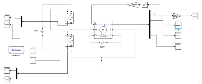
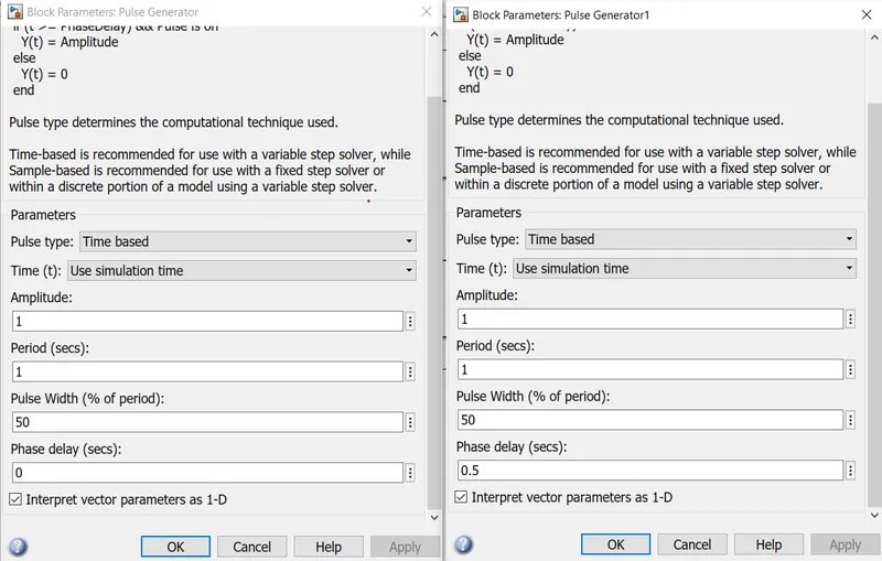
This model consists of Two IGBT/Diode pairs controlling the voltage of 240V fed to the DC motor. The DC motor is seperately excited by a 300V supply. The IGBTs are trigerred using pulse generators. The motor speed is converted as a fan load and fed back to motor as reference. All the specifications are given below:
Results:
After simulating the model for 1 sec, we get the following results-
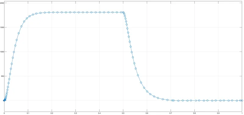
motor speed vs time
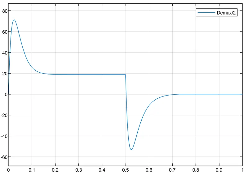
Armature current vs time
Inference:
From the graphs we can see both the quadrant operation which is forward motoring (0-0.5 sec)and forward braking(0.5-1 sec). Hence the model was simulated successfully.
-------------------------------------------------------------------------------------------------------------------------------
Q3. BLDC motor:
The Brushless DC motor consists of a permanent magnet acting as its rotor and an externally excited stator.A controller adjusts the phase and amplitude of the DC current pulses fed to the stator windings to control the speed and torque of the motor. This control system is an alternative to the mechanical commutator (brushes) used in many conventional electric motors.
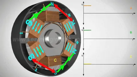
Because the controller implements the traditional brushes' functionality it needs to know the rotor's orientation relative to the stator coils. This is automatic in a brushed motor due to the fixed geometry of the rotor shaft and brushes. Some designs use Hall effect sensors to directly measure the rotor's position. Others measure the back-EMF in the undriven coils to infer the rotor position, eliminating the need for separate Hall effect sensors. These are therefore often called sensorless controller.
The advantages of a brushless motor over brushed motors are high power-to-weight ratio, high speed, nearly instantaneous control of speed (rpm) and torque, high efficiency, and low maintenance. Brushless motors find applications in such places as computer peripherals (disk drives, printers), hand-held power tools, and vehicles ranging from model aircraft to automobiles.