Week - 4
Q1. Washing Machine
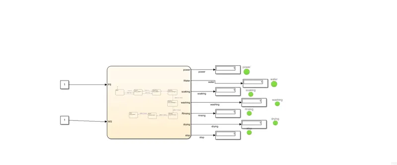
The following model was used for the state flow of washing machine:
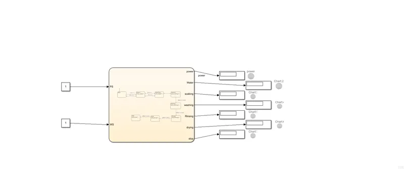
The inside of the chart block is as follows:
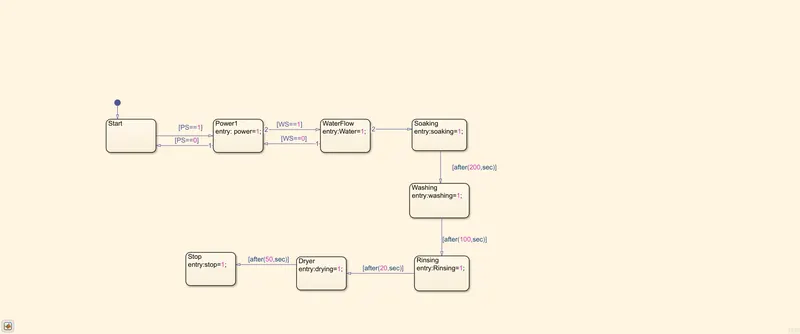
The chart was made by connecting different state flow blocks and giving the proper logic design as mentioned in the question. At the entry of various states we have declared variables with names same as state and initialized them to 1 letting us know that the state was reached.
Power Supply (PS) and water supply(WS) were given as inputs and the variables at different states were given as outputs.
Lamps were connected to each state indicating if they were reached or not.
The following result was generated when PS and WS was given as 1:
The following result was generated when PS=1 and WS=0:
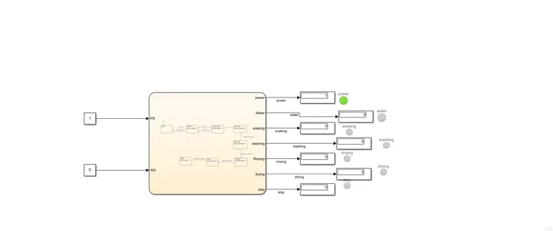
This indicates that the washing machine was resting at start state as there was no water supply.
------------------------------------------------------------------------------------------------------------------------------------------------------------------------------------------------------------------------------------------
Q2. Gear sgifting simulation
The model that was used for this is as follows:
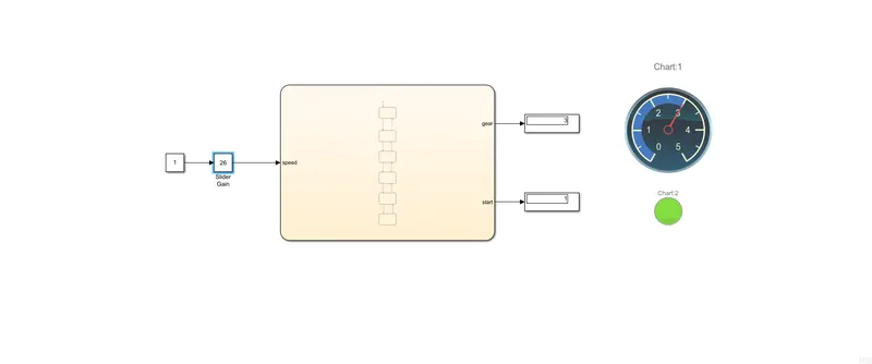

The gear change conditions were modelled according to the question.
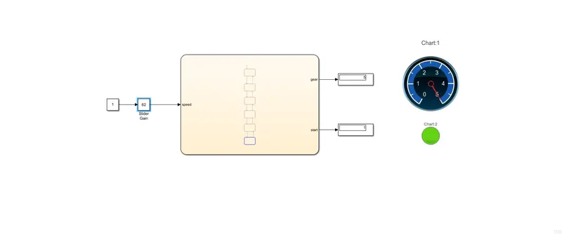
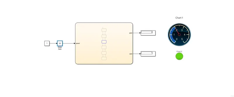
The state flow input was given using the slider gain using which the input speed was changed in between 0-100kmph and the outputs were the gear number and the variable start indicating if the car was started or not. A custom guage was added to depict the gear change.
Results:
The simulation time was given as inf and the slider gain was changed during simulation. Some of the results are as depicted: