Week -2
Q1. Doorbell using Solenoid Block
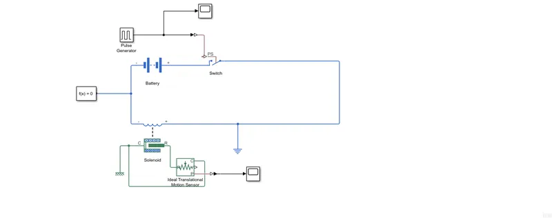
The above model was used for the simulation of a Solenoid whose plunger was used to hit a doorbell.
This model consisted of the following blocks:
1. A dc voltage supply
2. Switch with physical actuator
3. Pulse generator for providing actuating signals to switch
4. Solenoid
Solenoid is the generic term for a coil of wire used as an electromagnet. It also refers to any device that converts electrical energy to mechanical energy using a solenoid. The device creates a magnetic field from electric current and uses the magnetic field to create linear motion.
Aim:
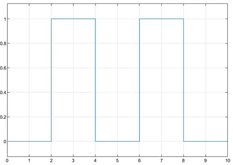
In this project, we fed DC voltage of 12V to the solenoid via a switch which we turned on for 2 seconds and then turned off for next 2 seconds. We tried to observe the linear displacement/motion of the plunger/arm of the solenoid.
Input Signal of switch actuator:
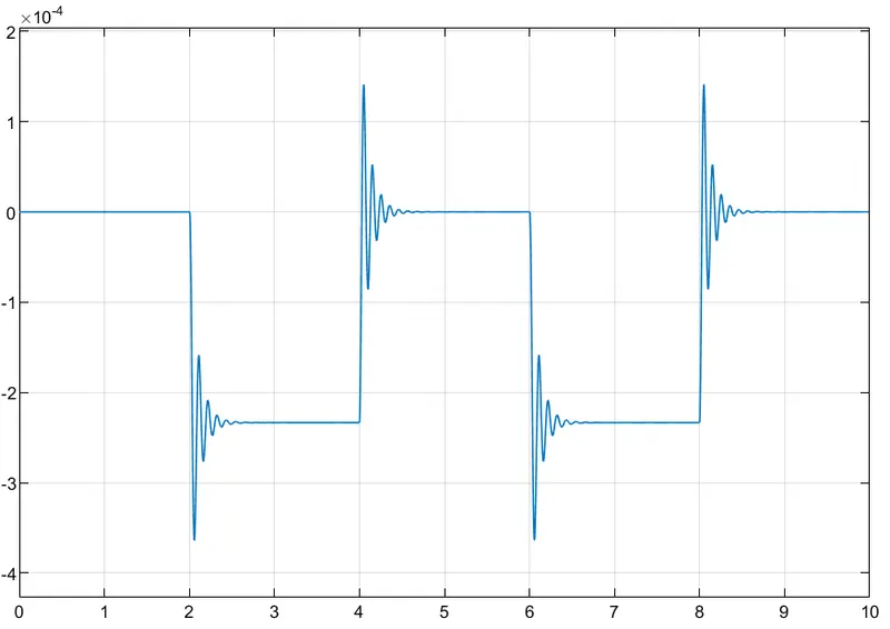
Output Observed on Ideal Translational Motion Sensor:
Inference:
It is observed from the simulation that when the switch was closed at t=2 sec,then the solenoid had got charged causing the physical displacement of its plunger/arm which then went and hit the doorbell causing the ringing. This continued till t=4 sec where the switch was opened and the plunger was back at it's initial position. The cycle repeats every four seconds. It should also be observed that the plunger experiences damping effect everytime its position changes.
-----------------------------------------------------------------------------------------------------------------------------------------------------------------------------------------------------------------
Q2. Turning cooling Fan of heater ON/OFF based on a thermistor:
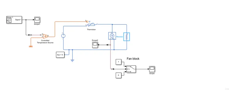
The above model was used to simulate a thermistor controlled fan for a heater.
Model consisted of the following blocks:
1. Temperature controlled source:
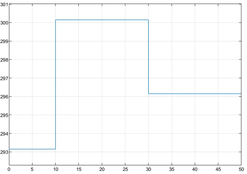
This was fed by a signal generator that provided 20 °C from 0 to 10 seconds, 27 °C from 10 to 30 seconds, 23 °C from 30 to 50 seconds modelling the temperature of the heater.
2. Thermistor :
The thermistor circuit consists of a Dc voltage source (12V), a heater resistance of 15 ohms and a voltmeter across it.
3. Fan :
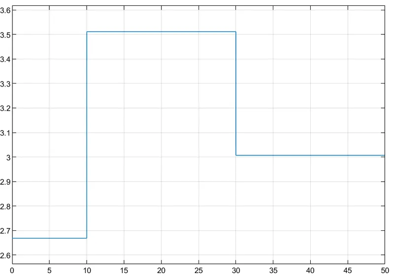
The fan was modelled as a switch whose threshold was set as 3.251V which is the volatage across the heater resistance at 25°C .
A thermistor is a type of resistor whose resistance is strongly dependent on temperature, more so than in standard resistors. The word is a combination of thermal and resistor.
Aim:
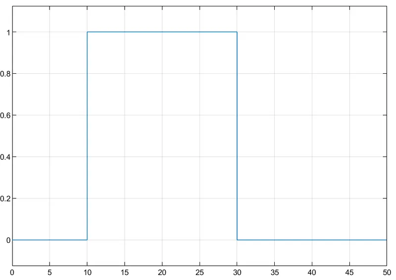
The model was simulated for a heater resistance connected with a thermistor whose temperature was varied over a period of 50s. The voltage across the heater was used as a input to turn the cooling fan ON/OFF.
Input temperature (in Kelvin):
Voltage across the Heater:
Output of Fan:
Inference:
It can be observed from the above graphs, that the fan turned ON between t=10 sec and t=30 sec because the voltage across the heater was greater than threshold (3.215V). All the other times as the volatge was less than threshold, the cooling fan remained OFF