Week-7 Challenge: DC Motor Control
DC MOTOR CONTROL
Aim: 1: To understand and explain Speed control of DC motor using BJT-H bridge and comment on shoot of armature current.
2: To explain the working of 2 quadrant chopper using simulink block.
3: To exploain the operation of BLDC motor.
Introduction: The the basic power electronic switches which used in the DC motor circuits are Thyristors, IGBT, BJT and MOSFET.
1: Tyristor: It consists of 3 P-N junctions and stable states as one ON-state and other OFF-state which can change from one state to other. they can control a large amount of voltage and power. they can be used in the power switching circuits, replacement circuits, level-dectector circuits, low-cost timer circuits, speed control circuits, oscillator circuits,logic circuits etc.
2: IGBT : it is called as Insulated-gate bipolar transistor(IGBT) which is a three terminal semiconductor device used as an electronic switch primarily having high efficiency and fast switching. it has four layers as (P-N-P-N) alternately.this is used in switching power supplies in high power applications, variable frequency drive, automobiles, welding machines etc.
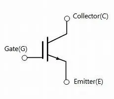
fig-1.1 :IBT
the IGBT can form complex waveforms with pulse width modulations having low pass filters that are helpful in switching aplifiers and industrial control systems. it turns on and off rapidly.
BJT: It is called as bipolar junction transistor that uses both the electrons and electron holes as a charge carrier. this allows small current that enters at one terminal to control as much large current flown in other two terminals allowing to amplify and switch.
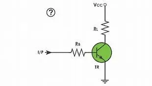
fig-1.2: BJT
MOSFET: It is widely used power electronic devices which doesn't require a continious flow of current providing high frequencies and high switching speeds. these are widely used in the automotive and telecommunication industry.

fig-1.3 Mosfet.
1: Speed control of a DC motor using BJTH-bridge:
In the given matlab model when BJT is used for power switching applications, operaters as IGBT. the switch is controlled by simulink signal. The DC motor uses the present model which simulates a fan type load where armature mean voltage can be varied from 0 to 240V when they varied from 0 to 100%
the two transistors switches simultaneously of H-bridge having 4 bjt diode pairs, where Q1 and Q4 are fired a positive and a positive voltage is applied D2, D3 operate as free-wheeling diodes as Q1 and Q2 are switched off.
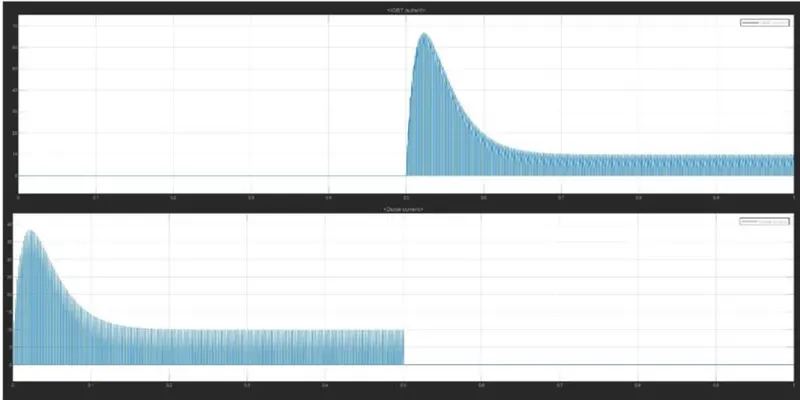
We can observe that in positive direction with 75%, at t=0.5sec and the armature voltage is suddenly reverse the motor runs in negative direction.
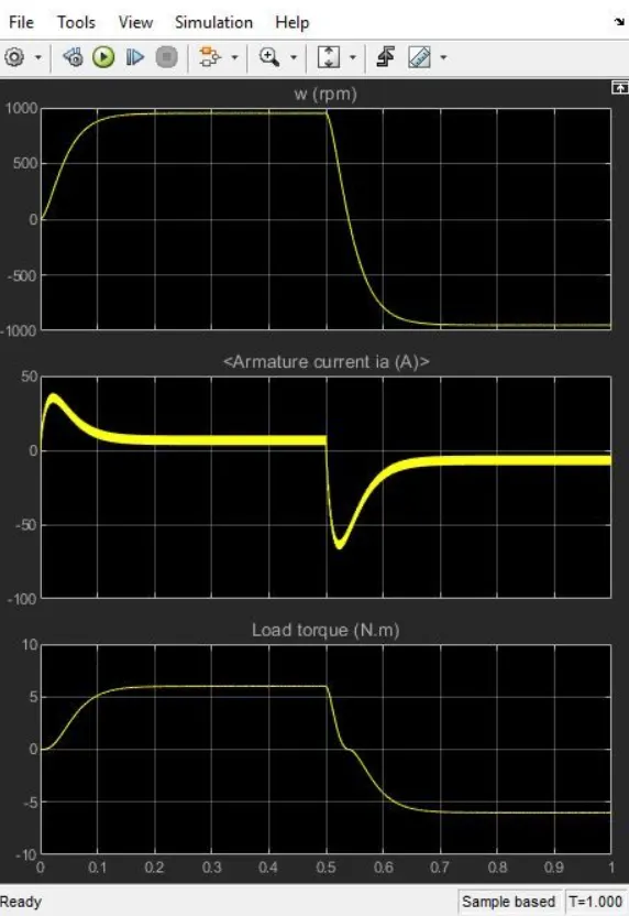
1b: The armature currrent shoot-up form the scope :
the decrease in the duty cycle will reduce spike during starting of DC motor. The resistance value of DC motor is less than 1 ohm anfd voltage supply will be 220-300V. thus a huge amount of current at the start of motor is observed and later the Eb value increases gradually but the La value decrease from start.
1c: Four-Quadrant Chopper DC Drive block and Comparing it with H-bridge model:
this consists of a 4-Quadrant supplied by DC and a chopper drive. this loop gives the armature current of the machine as an output. This can operate in 4- quadrants making this as an advantage and high switching freqency DC-DC, the current ripple is low. this uses Speed controller, Regulation Switch, Current Controller and chopper in it.
In Comparision with H-bridge this can work on all quadrants but H-bridge can work on only 2 quadrants. Regenerative breaking is not possible in h-bridge but possible in this.
2: Develop a 2-quadrant chopper using simulink & explain the working of same with relavant results:
A two-quadrant chopper gives varial DC output from a fixed DC input. in this there are two types of variations are present where the 1st and 2nd quadrants are functional in one varient and 1st and 4th in other.
From given reference model where a 200 HP DC motor is excited individually with a 150V DC source. To limit the DC voltage consisting of two regulators speed and current. the armature current ouputed by the speed regulator is used by the current controller to produce the required electromagnetic torque to reach the required speed. the current regulator controls the armature current by computing appropriate duty ratios of 5 kHz pulses.
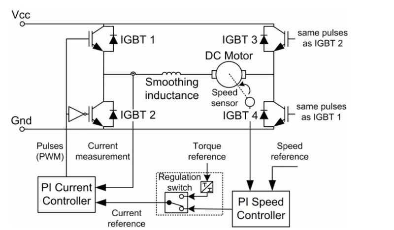
Fig-2.1: 2-Quadrant chopper circuit diagram.
we can observe from the simulink model that at the initial stage the voltage is 630V adjusted in using GUI block. the current and the voltage can be observed as well as IGBT pulses, motor speed on the scope. the initial torque is observed to be 814N.m at t=0 and 400 rpm. at t=2 sec the motor speed achives a steady state and frequency is 5kHz.
after t=2 the torque decreases directly to 100 N.m and motor speed comes back at 400 rpm, t=2.75 sec where a small electromagnetic torque is to be generated at 40 A and torque is reduced.
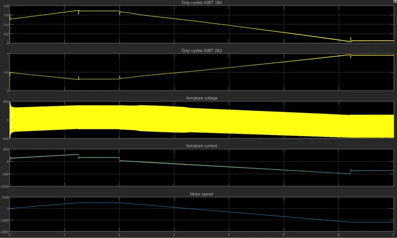
fig-2.2 scope results.
At t=2.75sec speed is a 200rpm the armature current goes to -160A where brakining action is observed.
At t=3.4sec, the speed is at 100rpm and current shoots to 40A
and finally at t=4sec, the speed remains constant.
Operation of BLDC motor:
A Brush Less DC motor os a permanent magnet synchronus electric motor which works by direct current. the armature current coils are switched by transistors at right rotor positions where armature filed in space quadrant with field poles. due to absence of bushes in BLDC motor the motors runs at high speeds giving an efficiency around 85-90%.
The BLDC motor works on the Lorentz force law which states as whatever a current carrying conductor placed in magnetic field it experiences a force as a reaction the magnet will get equal and opposite force. the conductor is stationary and magnets move. As the stator coils are electrically switched by supply source, it becomes electromagnet and starts producing a uniform field in air gap this converts the DC to AC voltage waveform due to interaction of the forces the rotor continues to rotate.
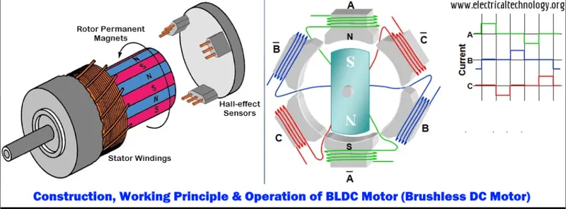
fig=3.1: BLDC circut.
From the above diagrams we can observe that motor produces torque because of attraction forces are being developed. based on the signal from sensor, the controller decides particular coils to energize. these sensors generate low and high level signals whenever rotor poles pass near to it.
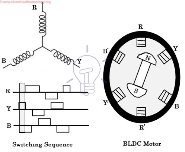
fig-3.2 BLDC switching states.